How to Use Greenline Tp4056 step up type C: Examples, Pinouts, and Specs
Introduction
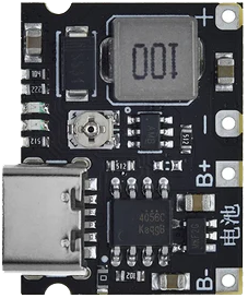
The Greenline TP4056 Step-Up Type-C module is a compact and efficient power management solution designed for charging lithium-ion batteries. It integrates the TP4056 chip, which ensures safe and reliable charging, and features a USB Type-C input for modern connectivity. This module also includes a step-up (boost) converter, allowing it to regulate and increase the output voltage as needed, making it ideal for powering devices that require higher voltages than the input source.
Explore Projects Built with Greenline Tp4056 step up type C


Explore Projects Built with Greenline Tp4056 step up type C
Common Applications and Use Cases
- Charging single-cell lithium-ion or lithium-polymer batteries.
- Powering portable electronics and DIY projects.
- Battery-powered IoT devices.
- Applications requiring USB Type-C connectivity for charging.
- Step-up voltage regulation for devices needing higher output voltages.
Technical Specifications
Key Technical Details
- Input Voltage (USB Type-C): 5V DC.
- Output Voltage (Boost Converter): Adjustable, typically 5V to 9V.
- Charging Current: Up to 1A (adjustable via onboard resistor).
- Battery Compatibility: Single-cell lithium-ion or lithium-polymer batteries (3.7V nominal).
- Protection Features: Overcharge, over-discharge, and short-circuit protection.
- Dimensions: Compact module, typically 25mm x 19mm.
Pin Configuration and Descriptions
The Greenline TP4056 Step-Up Type-C module has the following key pins and connections:
| Pin/Connection | Description |
|---|---|
| BAT+ | Positive terminal for the lithium battery connection. |
| BAT- | Negative terminal for the lithium battery connection. |
| OUT+ | Positive output terminal for the boosted voltage. |
| OUT- | Negative output terminal for the boosted voltage. |
| USB Type-C Port | Input for 5V DC power supply via USB Type-C connector. |
| PROG | Pin for adjusting the charging current by changing the onboard resistor value. |
Usage Instructions
How to Use the Component in a Circuit
Connect the Battery:
- Attach the positive terminal of the lithium-ion battery to the BAT+ pin.
- Attach the negative terminal of the battery to the BAT- pin.
Power the Module:
- Connect a 5V DC power source to the USB Type-C port. Ensure the power source can supply sufficient current (at least 1A).
Output Connection:
- Connect the device or circuit requiring boosted voltage to the OUT+ and OUT- pins.
Adjust Charging Current (Optional):
- To modify the charging current, replace the onboard resistor connected to the PROG pin. Refer to the TP4056 datasheet for resistor values corresponding to desired current levels.
Adjust Output Voltage (Optional):
- If the module supports adjustable output voltage, use the onboard potentiometer (if available) to set the desired voltage.
Important Considerations and Best Practices
- Ensure the battery is compatible with the module (single-cell lithium-ion or lithium-polymer, 3.7V nominal).
- Do not exceed the maximum input voltage of 5V to avoid damaging the module.
- Use proper heat dissipation if operating at high currents for extended periods.
- Verify the output voltage before connecting sensitive devices to prevent overvoltage damage.
- If using with an Arduino UNO or similar microcontroller, ensure the output voltage matches the microcontroller's input voltage requirements.
Example: Using with Arduino UNO
To power an Arduino UNO using the Greenline TP4056 Step-Up Type-C module:
- Connect the OUT+ pin to the Arduino's VIN pin.
- Connect the OUT- pin to the Arduino's GND pin.
- Ensure the output voltage is set to 7-9V (suitable for the Arduino UNO's voltage regulator).
Here is an example Arduino sketch to monitor the battery voltage using an analog input pin:
// Define the analog pin connected to the battery voltage divider
const int batteryPin = A0;

// Voltage divider resistor values (in ohms)
const float R1 = 10000.0; // Resistor connected to BAT+
const float R2 = 10000.0; // Resistor connected to GND

void setup() {
  Serial.begin(9600); // Initialize serial communication
}

void loop() {
  int rawValue = analogRead(batteryPin); // Read the analog value
  float voltage = (rawValue / 1023.0) * 5.0; // Convert to voltage (assuming 5V reference)

  // Calculate the actual battery voltage using the voltage divider formula
  float batteryVoltage = voltage * (R1 + R2) / R2;

  Serial.print("Battery Voltage: ");
  Serial.print(batteryVoltage);
  Serial.println(" V");

  delay(1000); // Wait for 1 second before the next reading
}
Troubleshooting and FAQs
Common Issues and Solutions
Module Overheating:
- Cause: Excessive current draw or insufficient heat dissipation.
- Solution: Reduce the load current or add a heatsink to the module.
Battery Not Charging:
- Cause: Incorrect battery connection or damaged battery.
- Solution: Verify the battery polarity and ensure the battery is functional.
No Output Voltage:
- Cause: Input power not supplied or output connections are loose.
- Solution: Check the USB Type-C power source and ensure all connections are secure.
Output Voltage Too Low or Unstable:
- Cause: Incorrect potentiometer adjustment or excessive load.
- Solution: Re-adjust the potentiometer and ensure the load is within the module's capacity.
FAQs
Can I use this module to charge multiple batteries in series? No, this module is designed for single-cell lithium-ion or lithium-polymer batteries only.
What is the maximum output current of the boost converter? The maximum output current depends on the input power and efficiency but is typically around 1A.
Can I use this module without a battery connected? No, the module requires a battery to function properly as it is designed for charging and boosting battery voltage.
Is the USB Type-C port compatible with fast charging? No, the USB Type-C port is for standard 5V input only and does not support fast charging protocols.