How to Use SEN0169-V2: Examples, Pinouts, and Specs
Introduction
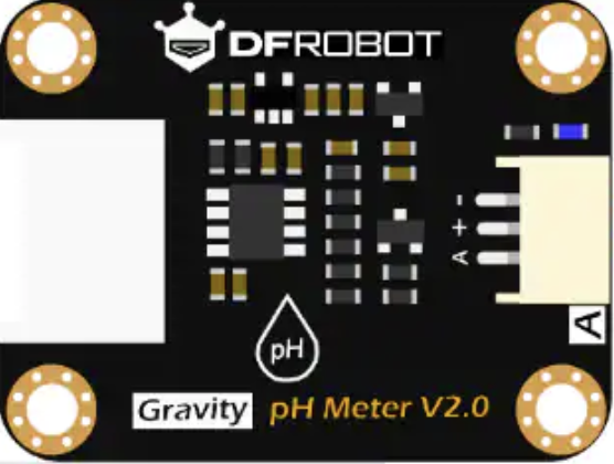
The SEN0169-V2 is a soil moisture sensor manufactured by DFRobot. It is designed to measure the volumetric water content in soil, providing an analog output that corresponds to the soil's moisture level. This sensor is widely used in agricultural applications, automated irrigation systems, and environmental monitoring projects. Its simple interface and reliable performance make it an excellent choice for both hobbyists and professionals.
Explore Projects Built with SEN0169-V2


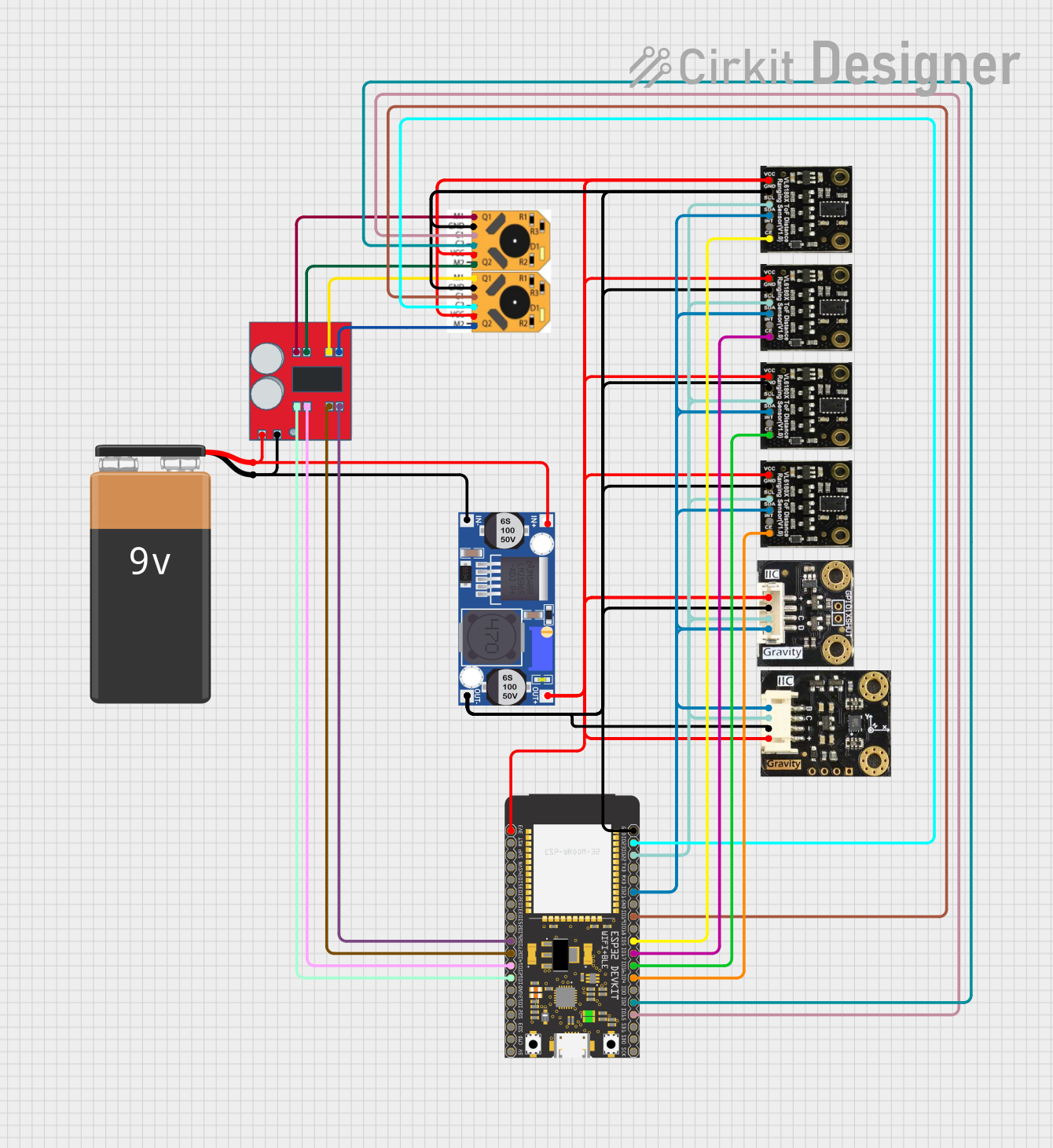
Explore Projects Built with SEN0169-V2
Common Applications
- Automated irrigation systems
- Greenhouse monitoring
- Agricultural research
- Environmental monitoring
- Gardening and landscaping projects
Technical Specifications
The SEN0169-V2 is a robust and easy-to-use sensor with the following technical specifications:
| Parameter | Value |
|---|---|
| Operating Voltage | 3.3V - 5.5V |
| Output Signal | Analog voltage (0-3.0V) |
| Current Consumption | < 20mA |
| Measurement Range | 0% - 100% soil moisture |
| Interface Type | Analog |
| Operating Temperature | 0°C - 60°C |
| Dimensions | 60mm x 20mm |
Pin Configuration
The SEN0169-V2 has a simple 3-pin interface:
| Pin | Name | Description |
|---|---|---|
| 1 | VCC | Power supply input (3.3V - 5.5V) |
| 2 | GND | Ground connection |
| 3 | AOUT | Analog output signal proportional to soil moisture |
Usage Instructions
Connecting the Sensor
- Power Supply: Connect the
VCCpin to a 3.3V or 5V power source, depending on your system's voltage. - Ground: Connect the
GNDpin to the ground of your circuit. - Analog Output: Connect the
AOUTpin to an analog input pin on your microcontroller (e.g., Arduino).
Example Circuit
Below is an example of how to connect the SEN0169-V2 to an Arduino UNO:
VCC→ 5V pin on ArduinoGND→ GND pin on ArduinoAOUT→ A0 pin on Arduino
Sample Arduino Code
The following code reads the analog output from the SEN0169-V2 and prints the soil moisture level to the Serial Monitor:
// Define the analog pin connected to the sensor
const int sensorPin = A0;

// Variable to store the sensor reading
int sensorValue;

void setup() {
  // Initialize the Serial Monitor for debugging
  Serial.begin(9600);
}

void loop() {
  // Read the analog value from the sensor
  sensorValue = analogRead(sensorPin);

  // Map the sensor value to a percentage (0-100%)
  int moisturePercent = map(sensorValue, 0, 1023, 0, 100);

  // Print the moisture percentage to the Serial Monitor
  Serial.print("Soil Moisture: ");
  Serial.print(moisturePercent);
  Serial.println("%");

  // Wait for 1 second before the next reading
  delay(1000);
}
Important Considerations
- Calibration: The sensor's output may vary depending on the soil type. Calibrate the sensor for your specific soil conditions by testing it in dry and saturated soil.
- Corrosion Prevention: The SEN0169-V2 is designed to resist corrosion, but prolonged exposure to water may still degrade its performance. Avoid leaving the sensor in wet soil for extended periods.
- Power Supply: Ensure the power supply voltage matches the sensor's operating range (3.3V - 5.5V) to avoid damage.
Troubleshooting and FAQs
Common Issues
No Output or Incorrect Readings
- Cause: Loose or incorrect wiring.
- Solution: Double-check all connections and ensure the sensor is properly powered.
Fluctuating Readings
- Cause: Electrical noise or unstable power supply.
- Solution: Use a decoupling capacitor (e.g., 0.1µF) between
VCCandGNDto stabilize the power supply.
Sensor Not Responding
- Cause: Damaged sensor or incorrect analog pin configuration.
- Solution: Test the sensor with a multimeter to verify its output. Ensure the correct analog pin is used in the code.
FAQs
Q: Can the SEN0169-V2 be used with a Raspberry Pi?
A: Yes, but since the Raspberry Pi does not have built-in analog input pins, you will need an external ADC (Analog-to-Digital Converter) to read the sensor's output.
Q: How do I clean the sensor?
A: Gently wipe the sensor probes with a soft, damp cloth. Avoid using abrasive materials or submerging the sensor in water.
Q: Can the sensor be buried in soil permanently?
A: While the SEN0169-V2 is corrosion-resistant, it is not designed for permanent installation. For long-term use, consider removing the sensor when not in use to extend its lifespan.