Cirkit Designer Logo
Cirkit Designer
Your all-in-one circuit design IDE
Home / 
Component Documentation

How to Use TRF-24G: Examples, Pinouts, and Specs


Image of TRF-24G
Cirkit Designer LogoDesign with TRF-24G in Cirkit Designer

Introduction

The TRF-24G is a low-power, 2.4 GHz RF transceiver designed for wireless communication applications. It supports multiple modulation schemes, including GFSK, and is ideal for short-range data transmission. This component is widely used in Internet of Things (IoT) devices, wireless sensor networks, remote controls, and other embedded systems requiring reliable and efficient wireless communication.

Explore Projects Built with TRF-24G

Use Cirkit Designer to design, explore, and prototype these projects online. Some projects support real-time simulation. Click "Open Project" to start designing instantly!
Satellite-Based Timing and Navigation System with SDR and Atomic Clock Synchronization
Image of GPS 시스템 측정 구성도_Confirm: A project utilizing TRF-24G in a practical application
This circuit appears to be a complex system involving power supply management, GPS and timing synchronization, and data communication. It includes a SI-TEX G1 Satellite Compass for GPS data, an XHTF1021 Atomic Rubidium Clock for precise timing, and Ettus USRP B200 units for software-defined radio communication. Power is supplied through various SMPS units and distributed via terminal blocks and DC jacks. Data communication is facilitated by Beelink MINI S12 N95 computers, RS232 splitters, and a 1000BASE-T Media Converter for network connectivity. RF Directional Couplers are used to interface antennas with the USRP units, and the entire system is likely contained within cases for protection and organization.
Cirkit Designer LogoOpen Project in Cirkit Designer
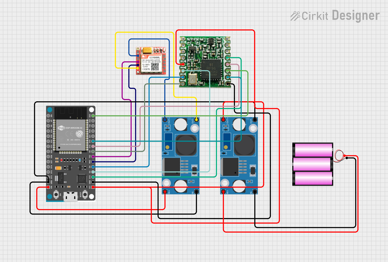
Dual-Mode LoRa and GSM Communication Device with ESP32
Image of modul gateway: A project utilizing TRF-24G in a practical application
This circuit features an ESP32 Devkit V1 microcontroller interfaced with an RFM95 LoRa transceiver module for long-range communication and a SIM800L GSM module for cellular connectivity. Two LM2596 step-down modules are used to regulate the 12V battery voltage down to 3.3V required by the ESP32, RFM95, and SIM800L. The ESP32 facilitates data exchange between the RFM95 and SIM800L, enabling the system to send/receive data over both LoRa and GSM networks.
Cirkit Designer LogoOpen Project in Cirkit Designer
Battery-Powered Emergency Alert System with NUCLEO-F072RB, SIM800L, and GPS NEO 6M
Image of women safety: A project utilizing TRF-24G in a practical application
This circuit is an emergency alert system that uses a NUCLEO-F072RB microcontroller to send SMS alerts and make calls via a SIM800L GSM module, while obtaining location data from a GPS NEO 6M module. The system is powered by a Li-ion battery and includes a TP4056 module for battery charging and protection, with a rocker switch to control power to the microcontroller.
Cirkit Designer LogoOpen Project in Cirkit Designer
Cellular-Enabled IoT Device with Real-Time Clock and Power Management
Image of LRCM PHASE 2 BASIC: A project utilizing TRF-24G in a practical application
This circuit features a LilyGo-SIM7000G module for cellular communication and GPS functionality, interfaced with an RTC DS3231 for real-time clock capabilities. It includes voltage sensing through two voltage sensor modules, and uses an 8-channel opto-coupler for isolating different parts of the circuit. Power management is handled by a buck converter connected to a DC power source and batteries, with a fuse for protection and a rocker switch for on/off control. Additionally, there's an LED for indication purposes.
Cirkit Designer LogoOpen Project in Cirkit Designer

Explore Projects Built with TRF-24G

Use Cirkit Designer to design, explore, and prototype these projects online. Some projects support real-time simulation. Click "Open Project" to start designing instantly!
Image of GPS 시스템 측정 구성도_Confirm: A project utilizing TRF-24G in a practical application
Satellite-Based Timing and Navigation System with SDR and Atomic Clock Synchronization
This circuit appears to be a complex system involving power supply management, GPS and timing synchronization, and data communication. It includes a SI-TEX G1 Satellite Compass for GPS data, an XHTF1021 Atomic Rubidium Clock for precise timing, and Ettus USRP B200 units for software-defined radio communication. Power is supplied through various SMPS units and distributed via terminal blocks and DC jacks. Data communication is facilitated by Beelink MINI S12 N95 computers, RS232 splitters, and a 1000BASE-T Media Converter for network connectivity. RF Directional Couplers are used to interface antennas with the USRP units, and the entire system is likely contained within cases for protection and organization.
Cirkit Designer LogoOpen Project in Cirkit Designer
Image of modul gateway: A project utilizing TRF-24G in a practical application
Dual-Mode LoRa and GSM Communication Device with ESP32
This circuit features an ESP32 Devkit V1 microcontroller interfaced with an RFM95 LoRa transceiver module for long-range communication and a SIM800L GSM module for cellular connectivity. Two LM2596 step-down modules are used to regulate the 12V battery voltage down to 3.3V required by the ESP32, RFM95, and SIM800L. The ESP32 facilitates data exchange between the RFM95 and SIM800L, enabling the system to send/receive data over both LoRa and GSM networks.
Cirkit Designer LogoOpen Project in Cirkit Designer
Image of women safety: A project utilizing TRF-24G in a practical application
Battery-Powered Emergency Alert System with NUCLEO-F072RB, SIM800L, and GPS NEO 6M
This circuit is an emergency alert system that uses a NUCLEO-F072RB microcontroller to send SMS alerts and make calls via a SIM800L GSM module, while obtaining location data from a GPS NEO 6M module. The system is powered by a Li-ion battery and includes a TP4056 module for battery charging and protection, with a rocker switch to control power to the microcontroller.
Cirkit Designer LogoOpen Project in Cirkit Designer
Image of LRCM PHASE 2 BASIC: A project utilizing TRF-24G in a practical application
Cellular-Enabled IoT Device with Real-Time Clock and Power Management
This circuit features a LilyGo-SIM7000G module for cellular communication and GPS functionality, interfaced with an RTC DS3231 for real-time clock capabilities. It includes voltage sensing through two voltage sensor modules, and uses an 8-channel opto-coupler for isolating different parts of the circuit. Power management is handled by a buck converter connected to a DC power source and batteries, with a fuse for protection and a rocker switch for on/off control. Additionally, there's an LED for indication purposes.
Cirkit Designer LogoOpen Project in Cirkit Designer

Common Applications:

  • IoT devices for home automation
  • Wireless sensor networks
  • Remote controls for consumer electronics
  • Industrial monitoring systems
  • Short-range data communication in embedded systems

Technical Specifications

Key Technical Details:

Parameter Value
Operating Frequency 2.4 GHz
Modulation Schemes GFSK, OOK
Data Rate Up to 2 Mbps
Operating Voltage 1.9V to 3.6V
Current Consumption 11 mA (TX mode), 13 mA (RX mode)
Sensitivity -90 dBm
Output Power Configurable, up to 0 dBm
Communication Range Up to 100 meters (line of sight)
Operating Temperature -40°C to +85°C
Package Type QFN-24

Pin Configuration and Descriptions:

Pin Number Pin Name Description
1 VDD Power supply input (1.9V to 3.6V)
2 GND Ground connection
3 RF_IN_OUT RF input/output for antenna connection
4 CE Chip Enable (active HIGH)
5 CSN Chip Select Not (active LOW)
6 SCK Serial Clock for SPI communication
7 MOSI Master Out Slave In for SPI communication
8 MISO Master In Slave Out for SPI communication
9 IRQ Interrupt request output
10-24 NC No connection (leave unconnected or grounded)

Usage Instructions

How to Use the TRF-24G in a Circuit:

  1. Power Supply: Connect the VDD pin to a regulated power source (1.9V to 3.6V) and the GND pin to the ground.
  2. Antenna Connection: Attach an appropriate 2.4 GHz antenna to the RF_IN_OUT pin for optimal signal transmission and reception.
  3. SPI Communication: Interface the TRF-24G with a microcontroller using the SPI pins (CSN, SCK, MOSI, MISO). Ensure the SPI clock speed does not exceed the component's maximum supported rate.
  4. Chip Enable: Use the CE pin to enable or disable the transceiver. Set CE HIGH to activate the device.
  5. Interrupt Handling: Connect the IRQ pin to a microcontroller GPIO pin to handle interrupts for events like data received or transmission complete.

Important Considerations:

  • Use decoupling capacitors (e.g., 0.1 µF) near the VDD pin to stabilize the power supply.
  • Ensure proper grounding to minimize noise and interference.
  • Use a matching network for the antenna to optimize RF performance.
  • Avoid placing the TRF-24G near high-frequency components or metal enclosures that may interfere with the RF signal.

Example Code for Arduino UNO:

#include <SPI.h>

// Define TRF-24G pin connections
#define CE_PIN 9    // Chip Enable pin
#define CSN_PIN 10  // Chip Select Not pin

void setup() {
  // Initialize SPI communication
  SPI.begin();
  
  // Configure CE and CSN pins as output
  pinMode(CE_PIN, OUTPUT);
  pinMode(CSN_PIN, OUTPUT);
  
  // Set CE and CSN to default states
  digitalWrite(CE_PIN, LOW);  // Disable transceiver
  digitalWrite(CSN_PIN, HIGH); // Deselect transceiver
  
  // Initialize serial communication for debugging
  Serial.begin(9600);
  Serial.println("TRF-24G Initialization Complete");
}

void loop() {
  // Example: Toggle CE pin to enable/disable the transceiver
  digitalWrite(CE_PIN, HIGH);  // Enable transceiver
  delay(1000);                 // Wait for 1 second
  digitalWrite(CE_PIN, LOW);   // Disable transceiver
  delay(1000);                 // Wait for 1 second
}

Troubleshooting and FAQs

Common Issues and Solutions:

  1. No Communication Between Devices:

    • Ensure both devices are configured with the same frequency and data rate.
    • Verify the SPI connections and ensure proper wiring.
    • Check the antenna connection and ensure it is suitable for 2.4 GHz.
  2. High Current Consumption:

    • Verify that the TRF-24G is not stuck in TX mode. Use the CE pin to control the transceiver state.
    • Check for shorts or incorrect wiring in the circuit.
  3. Poor Signal Range:

    • Ensure a clear line of sight between devices.
    • Use a properly tuned antenna and matching network.
    • Avoid interference from other 2.4 GHz devices or sources.
  4. Interrupts Not Triggering:

    • Verify the IRQ pin connection to the microcontroller.
    • Ensure the microcontroller is configured to handle external interrupts.

FAQs:

  • Q: Can the TRF-24G operate at 5V?
    A: No, the TRF-24G operates within a voltage range of 1.9V to 3.6V. Use a voltage regulator if your system operates at 5V.

  • Q: What is the maximum data rate supported?
    A: The TRF-24G supports data rates up to 2 Mbps.

  • Q: Can I use the TRF-24G for long-range communication?
    A: The TRF-24G is designed for short-range communication, with a maximum range of approximately 100 meters in line-of-sight conditions.

  • Q: Is the TRF-24G compatible with Arduino?
    A: Yes, the TRF-24G can be interfaced with Arduino boards using SPI communication.

This concludes the documentation for the TRF-24G.