How to Use GPS NEO 6M: Examples, Pinouts, and Specs
Introduction
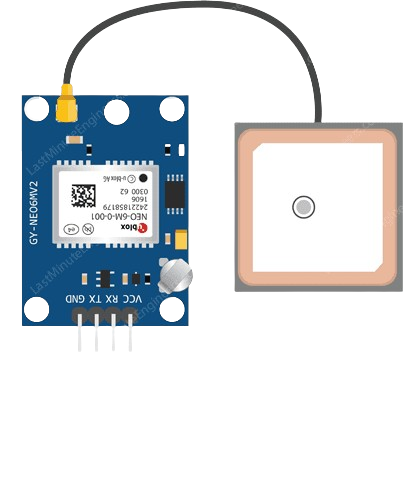
The GPS NEO 6M is a compact and reliable GPS module designed to provide accurate positioning and timing information. It is widely used in navigation, tracking, and location-based applications. The module integrates a high-performance GPS receiver with a built-in antenna, making it suitable for a variety of projects, including drones, vehicle tracking systems, and IoT devices.
Common applications of the GPS NEO 6M include:
- Navigation systems for vehicles and drones
- Real-time location tracking
- Geofencing and asset tracking
- Time synchronization for IoT devices
Explore Projects Built with GPS NEO 6M


Explore Projects Built with GPS NEO 6M
Technical Specifications
The GPS NEO 6M module is equipped with advanced features to ensure high accuracy and reliability. Below are its key technical specifications:
| Parameter | Specification |
|---|---|
| Operating Voltage | 2.7V to 3.6V (typically 3.3V) |
| Power Consumption | 45mA (typical) |
| Communication Protocol | UART (default) and I2C |
| Baud Rate (default) | 9600 bps |
| Position Accuracy | 2.5 meters CEP |
| Time to First Fix (TTFF) | Cold Start: 27s, Hot Start: 1s |
| Operating Temperature | -40°C to +85°C |
| Dimensions | 16 x 12.2 x 2.4 mm |
Pin Configuration and Descriptions
The GPS NEO 6M module typically comes with a 4-pin interface. Below is the pinout description:
| Pin | Name | Description |
|---|---|---|
| 1 | VCC | Power supply input (3.3V recommended) |
| 2 | GND | Ground connection |
| 3 | TX | UART Transmit pin (sends GPS data to the host device) |
| 4 | RX | UART Receive pin (receives commands from the host) |
Usage Instructions
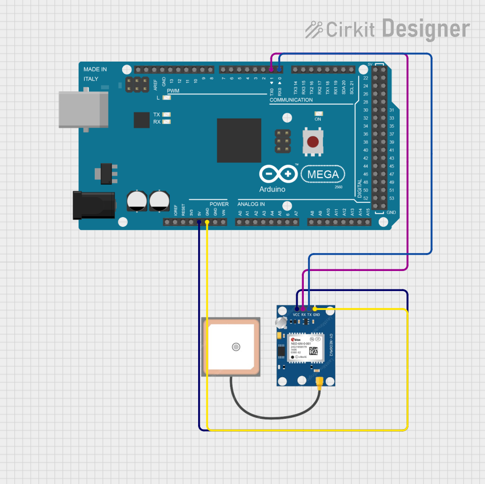
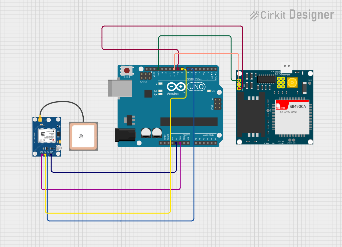
How to Use the GPS NEO 6M in a Circuit
- Power the Module: Connect the VCC pin to a 3.3V power source and the GND pin to ground.
- Connect UART Pins:
- Connect the TX pin of the GPS module to the RX pin of your microcontroller (e.g., Arduino UNO).
- Connect the RX pin of the GPS module to the TX pin of your microcontroller.
- Antenna Placement: Ensure the module's antenna has a clear view of the sky for optimal satellite reception.
- Configure Baud Rate: The default baud rate is 9600 bps. Ensure your microcontroller's UART settings match this.
Important Considerations and Best Practices
- Use a level shifter if interfacing the module with a 5V microcontroller to avoid damaging the GPS module.
- Place the module away from sources of electromagnetic interference (e.g., motors, power supplies).
- Allow the module sufficient time to acquire satellite signals, especially during a cold start.
Example Code for Arduino UNO
Below is an example of how to interface the GPS NEO 6M with an Arduino UNO to read GPS data:
#include <SoftwareSerial.h>

// Define RX and TX pins for SoftwareSerial
SoftwareSerial gpsSerial(4, 3); // RX = Pin 4, TX = Pin 3

void setup() {
  Serial.begin(9600); // Initialize Serial Monitor at 9600 bps
  gpsSerial.begin(9600); // Initialize GPS module at 9600 bps

  Serial.println("GPS NEO 6M Test");
}

void loop() {
  // Check if data is available from the GPS module
  while (gpsSerial.available()) {
    char gpsData = gpsSerial.read(); // Read one character from GPS
    Serial.print(gpsData); // Print the character to Serial Monitor
  }
}
Notes:
- The
SoftwareSeriallibrary is used to create a secondary serial port for the GPS module. - Ensure the RX and TX pins in the code match your wiring.
Troubleshooting and FAQs
Common Issues and Solutions
No GPS Data Received
- Cause: Incorrect wiring or baud rate mismatch.
- Solution: Double-check the connections and ensure the baud rate is set to 9600 bps.
Poor Satellite Signal
- Cause: Obstructed antenna or indoor usage.
- Solution: Place the module outdoors or near a window with a clear view of the sky.
Module Not Powering On
- Cause: Insufficient power supply.
- Solution: Ensure the VCC pin is supplied with 3.3V and the GND pin is properly connected.
Data Appears as Gibberish
- Cause: Baud rate mismatch between the GPS module and the microcontroller.
- Solution: Verify that both devices are set to the same baud rate (default: 9600 bps).
FAQs
Q: Can the GPS NEO 6M work indoors?
A: While the module can function indoors, its performance may be significantly reduced due to limited satellite visibility. For best results, use it outdoors or near a window.
Q: How many satellites does the GPS NEO 6M support?
A: The module can track up to 22 satellites simultaneously.
Q: Can I use the GPS NEO 6M with a 5V microcontroller?
A: Yes, but you must use a level shifter to step down the 5V signals to 3.3V to avoid damaging the module.
Q: How long does it take to get a GPS fix?
A: A cold start typically takes 27 seconds, while a hot start can take as little as 1 second under optimal conditions.