
How to Use Digital RGB LED Module v1.0: Examples, Pinouts, and Specs
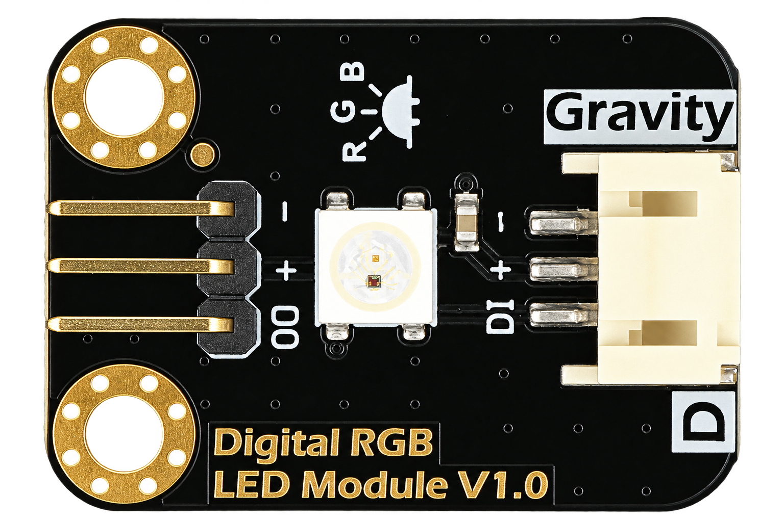
 Design with Digital RGB LED Module v1.0 in Cirkit Designer
Introduction
The Digital RGB LED Module v1.0 by DFRobot is a versatile lighting module featuring individually addressable RGB LEDs. Each LED can display a wide range of colors and brightness levels, making it ideal for creating dynamic lighting effects. The module is controlled digitally, allowing precise control over each LED's color and intensity.
Explore Projects Built with Digital RGB LED Module v1.0
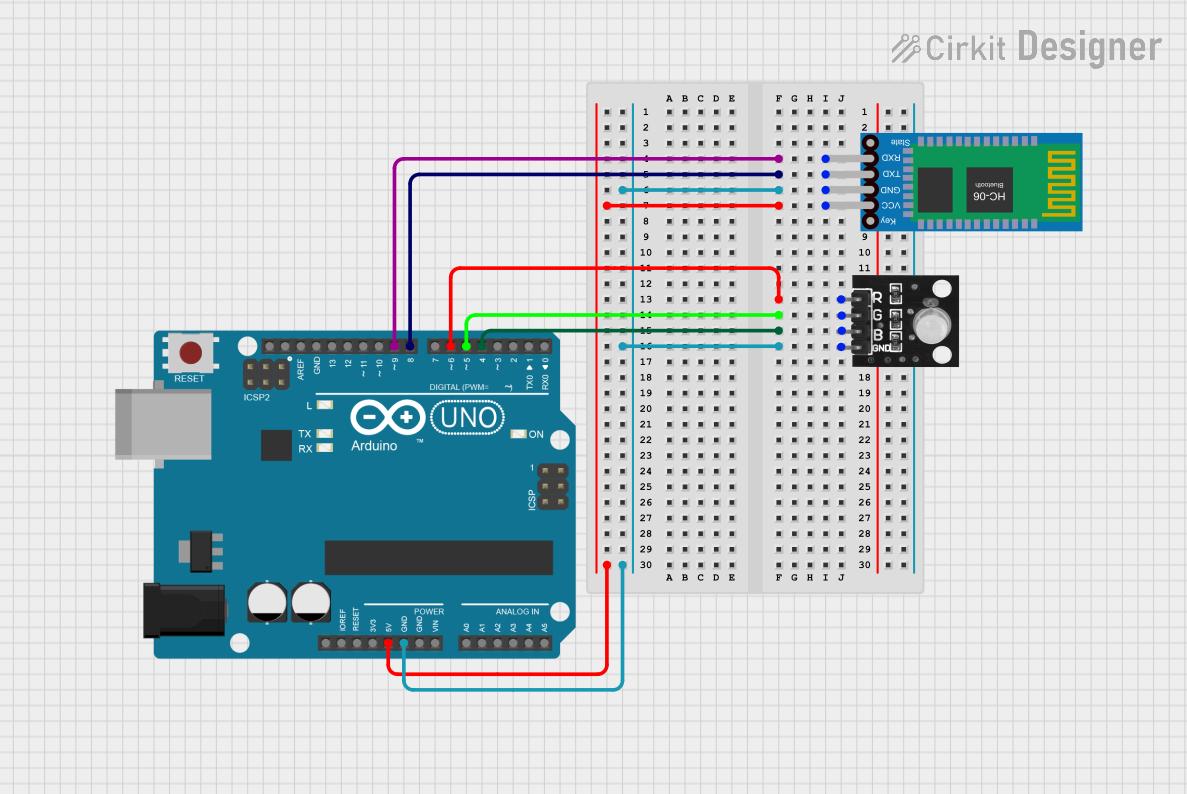 Open Project in Cirkit Designer
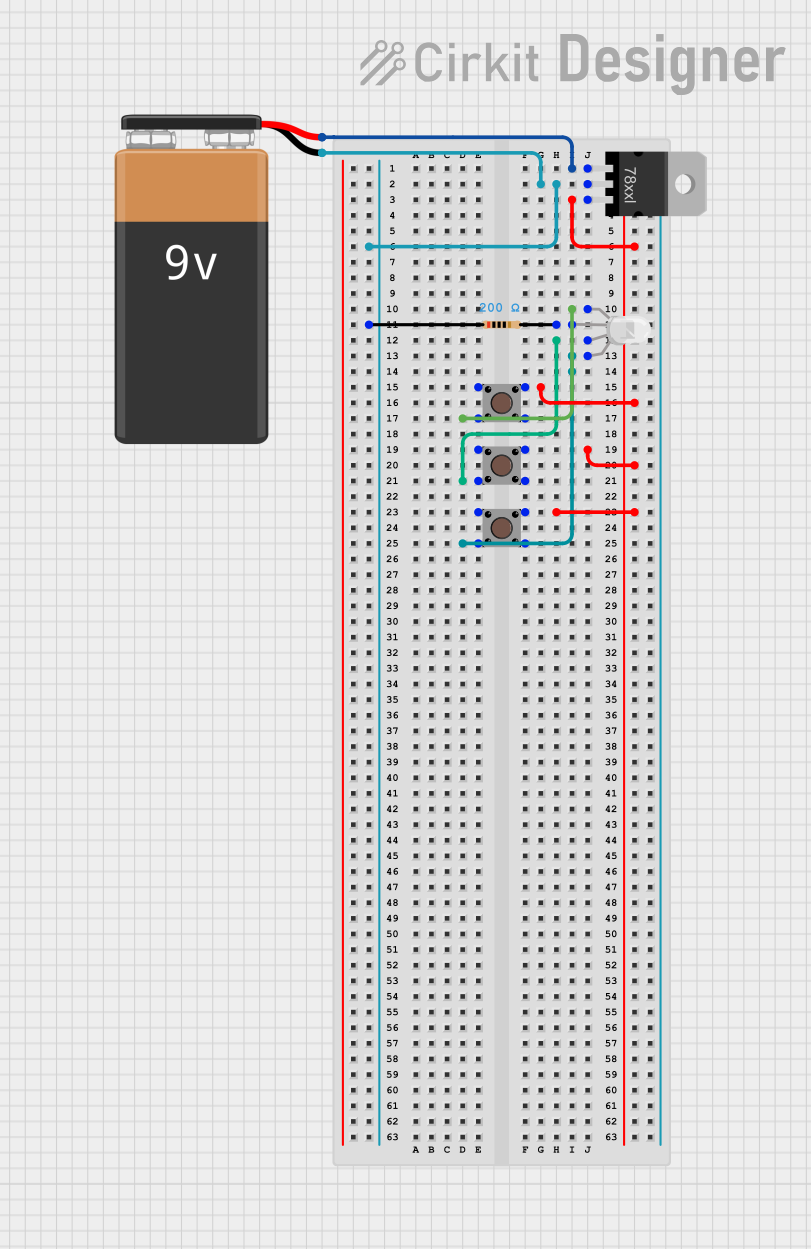 Open Project in Cirkit Designer
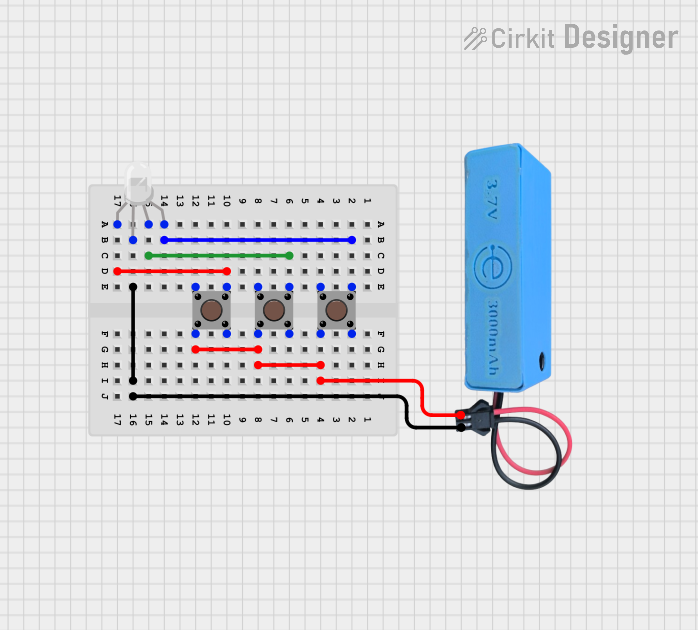 Open Project in Cirkit Designer
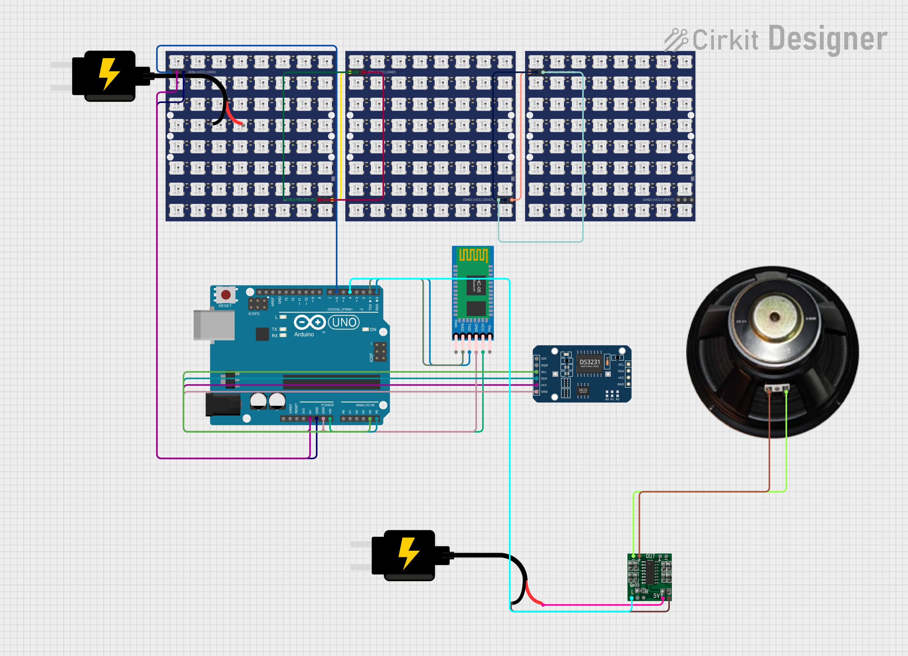 Open Project in Cirkit Designer
Explore Projects Built with Digital RGB LED Module v1.0
Open Project in Cirkit DesignerOpen Project in Cirkit DesignerOpen Project in Cirkit DesignerOpen Project in Cirkit DesignerCommon Applications and Use Cases
- Decorative lighting for projects and installations
- Status indicators for electronic devices
- Interactive displays and signage
- DIY projects, including wearables and robotics
- Gaming setups and ambient lighting
Technical Specifications
The following table outlines the key technical details of the Digital RGB LED Module v1.0:
| Parameter | Specification |
|---|---|
| Operating Voltage | 5V DC |
| Operating Current | 20mA per LED (typical) |
| LED Type | WS2812B (individually addressable) |
| Communication Protocol | Single-wire digital control |
| Number of LEDs | 1 (per module) |
| Dimensions | 25mm x 25mm x 3mm |
| Operating Temperature | -25°C to 80°C |
Pin Configuration and Descriptions
The module has three pins for connection, as described in the table below:
| Pin | Name | Description |
|---|---|---|
| 1 | VCC | Power supply input (5V DC) |
| 2 | GND | Ground connection |
| 3 | DIN | Digital input for data signal (connect to microcontroller) |
Usage Instructions
How to Use the Component in a Circuit
- Power Supply: Connect the
VCCpin to a 5V DC power source and theGNDpin to the ground of your circuit. - Data Signal: Connect the
DINpin to a digital output pin of your microcontroller (e.g., Arduino UNO). - Resistor and Capacitor: For stable operation, place a 330-ohm resistor between the microcontroller's output pin and the
DINpin. Additionally, connect a 1000µF capacitor across theVCCandGNDpins to prevent voltage spikes. - Programming: Use a library like the Adafruit NeoPixel library to control the LEDs.
Important Considerations and Best Practices
- Ensure the power supply can handle the total current draw of all connected modules.
- Avoid exceeding the operating voltage of 5V to prevent damage to the module.
- Use a common ground between the microcontroller and the module for proper operation.
- If chaining multiple modules, connect the
DOUTpin of one module to theDINpin of the next.
Example Code for Arduino UNO
Below is an example code snippet to control the Digital RGB LED Module v1.0 using the Adafruit NeoPixel library:
#include <Adafruit_NeoPixel.h>

// Define the pin connected to the DIN pin of the module
#define LED_PIN 6

// Define the number of LEDs in the module (1 for this module)
#define NUM_LEDS 1

// Create a NeoPixel object
Adafruit_NeoPixel strip = Adafruit_NeoPixel(NUM_LEDS, LED_PIN, NEO_GRB + NEO_KHZ800);

void setup() {
  strip.begin(); // Initialize the NeoPixel library
  strip.show();  // Turn off all LEDs initially
}

void loop() {
  // Set the LED to red
  strip.setPixelColor(0, strip.Color(255, 0, 0)); // Red color
  strip.show(); // Update the LED
  delay(1000);  // Wait for 1 second

  // Set the LED to green
  strip.setPixelColor(0, strip.Color(0, 255, 0)); // Green color
  strip.show(); // Update the LED
  delay(1000);  // Wait for 1 second

  // Set the LED to blue
  strip.setPixelColor(0, strip.Color(0, 0, 255)); // Blue color
  strip.show(); // Update the LED
  delay(1000);  // Wait for 1 second
}
Troubleshooting and FAQs
Common Issues and Solutions
LED Not Lighting Up:
- Ensure the
VCCandGNDpins are connected properly. - Verify that the
DINpin is receiving a valid data signal from the microcontroller. - Check for loose or broken connections.
- Ensure the
Incorrect Colors Displayed:
- Confirm that the correct color order (e.g., GRB or RGB) is specified in the code.
- Ensure the data signal is not distorted by using a resistor (330 ohms) between the microcontroller and the
DINpin.
Flickering or Unstable Operation:
- Add a 1000µF capacitor across the
VCCandGNDpins to stabilize the power supply. - Verify that the power supply can handle the current requirements of the module.
- Add a 1000µF capacitor across the
Multiple Modules Not Working:
- Check the connection between the
DOUTpin of one module and theDINpin of the next. - Ensure the data signal is not degraded over long distances by using a level shifter if necessary.
- Check the connection between the
FAQs
Q: Can I chain multiple modules together?
A: Yes, you can chain multiple modules by connecting the DOUT pin of one module to the DIN pin of the next. Ensure the power supply can handle the total current draw.
Q: What is the maximum number of modules I can chain?
A: The maximum number depends on the microcontroller's memory and the power supply. For Arduino UNO, you can typically control up to 500 LEDs.
Q: Can I power the module with a voltage higher than 5V?
A: No, the module is designed to operate at 5V DC. Exceeding this voltage may damage the LEDs.
Q: Do I need a specific library to control the module?
A: While you can write your own code, it is recommended to use the Adafruit NeoPixel library for ease of use and reliability.