How to Use rasp: Examples, Pinouts, and Specs
Introduction
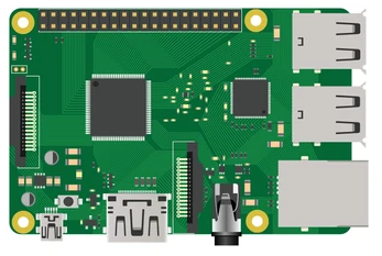
The Raspberry Pi (commonly referred to as "Rasp") is a compact, affordable, and versatile single-board computer developed by the Raspberry Pi Foundation. It is widely used in educational, hobbyist, and professional projects due to its flexibility and ease of use. The Rasp is equipped with General Purpose Input/Output (GPIO) pins, making it ideal for hardware interfacing, robotics, Internet of Things (IoT) applications, and more. It supports various operating systems, including Raspberry Pi OS (formerly Raspbian), Ubuntu, and others.
Explore Projects Built with rasp
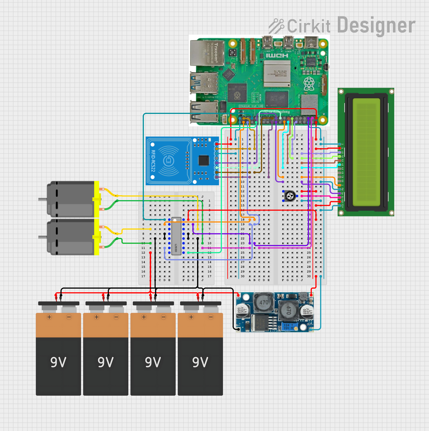
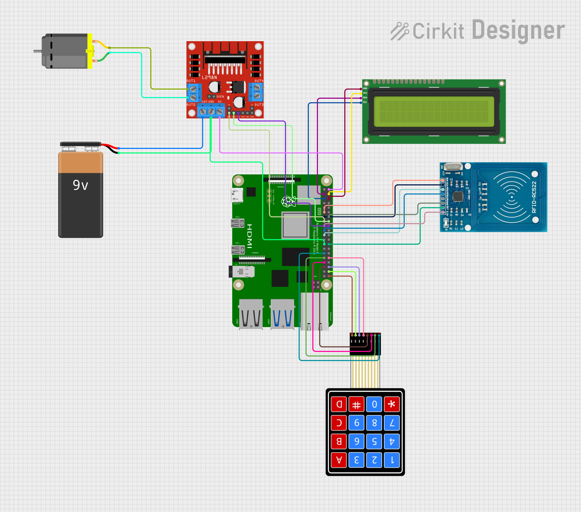
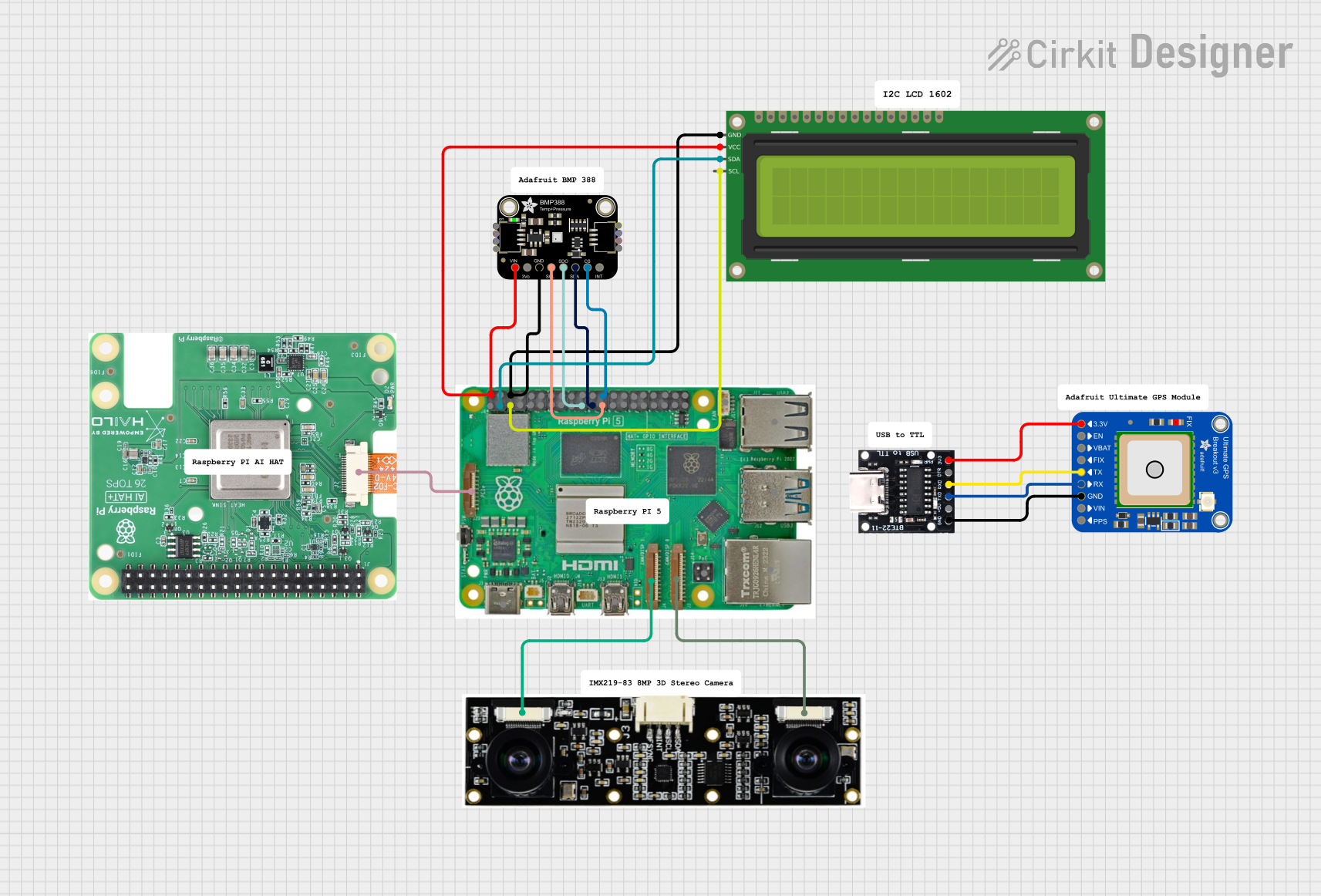
Explore Projects Built with rasp
Common Applications and Use Cases
- Programming and Education: Ideal for learning programming languages like Python, C++, and Java.
- IoT Projects: Used in smart home systems, environmental monitoring, and automation.
- Robotics: Controls motors, sensors, and other hardware components.
- Media Centers: Can be configured as a media server or streaming device.
- Prototyping: Serves as a platform for testing and developing hardware and software solutions.
Technical Specifications
Below are the key technical details for the Raspberry Pi:
General Specifications
| Feature | Details |
|---|---|
| Processor | Quad-core ARM Cortex-A series (varies by model) |
| RAM | 1GB, 2GB, 4GB, or 8GB LPDDR4 (depending on model) |
| Storage | MicroSD card slot for OS and data storage |
| Connectivity | Wi-Fi, Bluetooth, Ethernet (varies by model) |
| GPIO Pins | 40-pin header (3.3V logic) |
| Power Supply | 5V via USB-C (or micro-USB for older models), typically 2.5A to 3A required |
| Video Output | HDMI, micro-HDMI, or composite video (depending on model) |
| USB Ports | USB 2.0 and/or USB 3.0 (varies by model) |
| Audio | 3.5mm audio jack and HDMI audio output |
GPIO Pin Configuration
The Raspberry Pi features a 40-pin GPIO header. Below is a summary of the pin configuration:
| Pin Number | Pin Name | Description |
|---|---|---|
| 1 | 3.3V Power | 3.3V power supply |
| 2 | 5V Power | 5V power supply |
| 3 | GPIO2 (SDA1) | I2C Data |
| 4 | 5V Power | 5V power supply |
| 5 | GPIO3 (SCL1) | I2C Clock |
| 6 | Ground | Ground |
| 7 | GPIO4 | General-purpose I/O |
| 8 | GPIO14 (TXD) | UART Transmit |
| 9 | Ground | Ground |
| 10 | GPIO15 (RXD) | UART Receive |
| ... | ... | ... |
| 39 | Ground | Ground |
| 40 | GPIO21 | General-purpose I/O |
For the full GPIO pinout, refer to the official Raspberry Pi documentation.
Usage Instructions
How to Use the Raspberry Pi in a Circuit
- Powering the Raspberry Pi: Use a 5V power supply with sufficient current (2.5A to 3A) via the USB-C or micro-USB port.
- Connecting Peripherals: Attach a monitor via HDMI, a keyboard and mouse via USB, and a microSD card with the operating system installed.
- Using GPIO Pins: Connect sensors, LEDs, or other components to the GPIO pins. Be cautious of voltage levels (3.3V logic).
- Networking: Connect to the internet via Wi-Fi or Ethernet for remote access and updates.
Important Considerations and Best Practices
- Voltage Levels: The GPIO pins operate at 3.3V logic. Avoid connecting 5V directly to GPIO pins to prevent damage.
- Static Electricity: Handle the board with care to avoid static discharge, which can damage components.
- Cooling: For intensive tasks, consider using a heatsink or fan to prevent overheating.
- Shutdown Procedure: Always shut down the Raspberry Pi properly via the operating system to avoid corrupting the microSD card.
Example: Blinking an LED with GPIO and Python
Below is an example of how to blink an LED connected to GPIO pin 17 using Python:
Import necessary libraries
import RPi.GPIO as GPIO # Library for GPIO control import time # Library for time delays
Pin configuration
LED_PIN = 17 # GPIO pin where the LED is connected
GPIO setup
GPIO.setmode(GPIO.BCM) # Use Broadcom pin numbering GPIO.setup(LED_PIN, GPIO.OUT) # Set the pin as an output
try: while True: GPIO.output(LED_PIN, GPIO.HIGH) # Turn the LED on time.sleep(1) # Wait for 1 second GPIO.output(LED_PIN, GPIO.LOW) # Turn the LED off time.sleep(1) # Wait for 1 second except KeyboardInterrupt: # Clean up GPIO settings on exit GPIO.cleanup()
Troubleshooting and FAQs
Common Issues and Solutions
The Raspberry Pi does not boot:
- Ensure the microSD card is properly inserted and contains a valid operating system image.
- Check the power supply for sufficient voltage and current.
GPIO pins are not working:
- Verify the pin configuration in your code.
- Ensure the connected components are functioning and wired correctly.
Overheating:
- Use a heatsink or fan for cooling.
- Avoid running resource-intensive tasks for extended periods without proper cooling.
No display output:
- Check the HDMI cable and monitor connection.
- Ensure the correct HDMI port is selected on the monitor.
FAQs
Can I power the Raspberry Pi via GPIO pins? Yes, you can power the Raspberry Pi via the 5V and Ground GPIO pins, but this bypasses the onboard voltage regulation and protection circuits. Use caution.
What operating systems are supported? The Raspberry Pi supports Raspberry Pi OS, Ubuntu, and other Linux-based distributions. Some models also support Windows IoT Core.
Can I use the Raspberry Pi for machine learning? Yes, the Raspberry Pi can run lightweight machine learning models, especially with hardware accelerators like the Google Coral USB Accelerator.
For additional support, refer to the official Raspberry Pi documentation or community forums.