How to Use Laser Diode Module: Examples, Pinouts, and Specs
Introduction
A Laser Diode Module is a compact device that emits coherent light when an electric current passes through it. It is widely used in applications requiring precision and efficiency. Common use cases include optical communication, laser printing, barcode scanning, medical devices, and alignment tools. Its small size, high efficiency, and ability to produce focused light make it an essential component in various industries.
Explore Projects Built with Laser Diode Module
Explore Projects Built with Laser Diode Module
Technical Specifications
Below are the key technical details and pin configuration for a typical Laser Diode Module:
Key Technical Details
| Parameter | Value |
|---|---|
| Operating Voltage | 3V to 5V |
| Operating Current | 20mA to 40mA |
| Wavelength | 650nm (red light) |
| Output Power | <5mW |
| Beam Divergence | <1.2 mrad |
| Operating Temperature | -10°C to 50°C |
| Dimensions | Typically 6mm x 12mm (varies) |
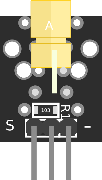
Pin Configuration
| Pin Number | Pin Name | Description |
|---|---|---|
| 1 | VCC | Positive power supply (3V to 5V) |
| 2 | GND | Ground connection |
| 3 | Signal (optional) | Modulation input for controlling the laser output (if available) |
Note: Some Laser Diode Modules may only have two pins (VCC and GND). Always refer to the datasheet of your specific module for accurate pin details.
Usage Instructions
How to Use the Laser Diode Module in a Circuit
- Power Supply: Connect the VCC pin to a 3V to 5V DC power source and the GND pin to the ground. Ensure the power supply is stable and within the specified voltage range.
- Optional Modulation: If the module has a signal pin, you can use it to modulate the laser output using a PWM signal or other control logic.
- Current Limiting: Use a current-limiting resistor or a constant current driver to prevent overdriving the laser diode, which can damage it.
- Heat Management: Ensure proper heat dissipation, especially for high-power modules, to maintain performance and longevity.
Important Considerations and Best Practices
- Eye Safety: Never look directly into the laser beam or point it at others. Use appropriate safety goggles if necessary.
- Polarity: Double-check the polarity of the connections before powering the module to avoid damage.
- Mounting: Secure the module in a stable position to maintain alignment and prevent accidental movement.
- Environment: Avoid using the module in environments with excessive dust, moisture, or extreme temperatures.
Example: Connecting to an Arduino UNO
Below is an example of how to connect and control a Laser Diode Module using an Arduino UNO:
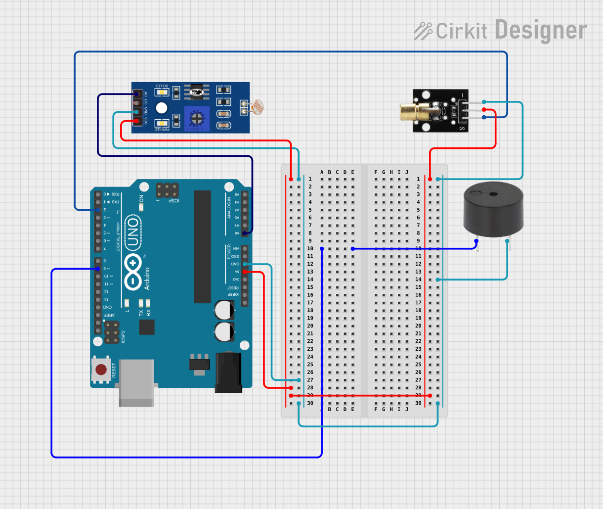
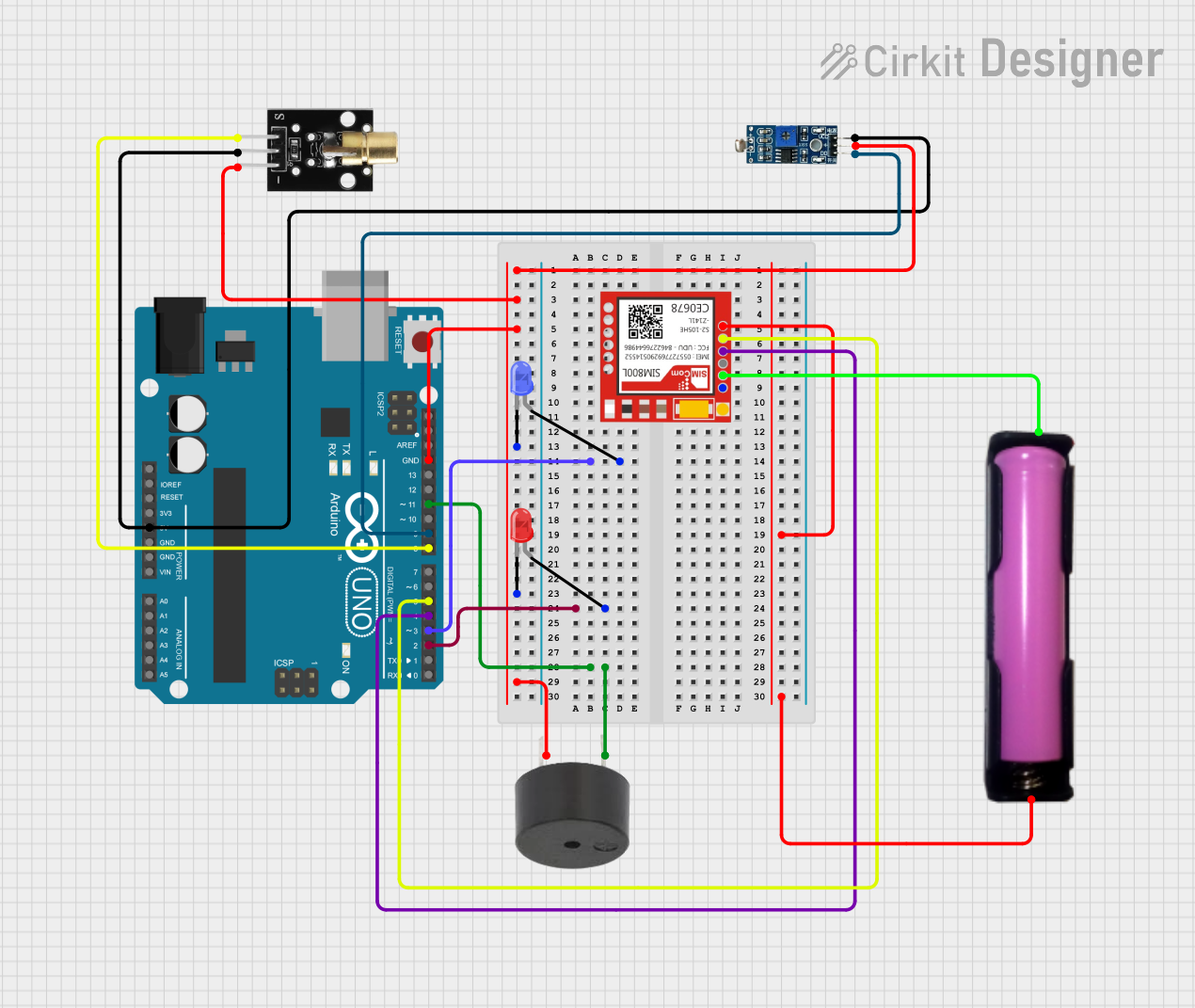
Circuit Diagram
- Connect the VCC pin of the Laser Diode Module to the 5V pin on the Arduino.
- Connect the GND pin of the module to the GND pin on the Arduino.
- If the module has a signal pin, connect it to a PWM-capable pin on the Arduino (e.g., pin 9).
Arduino Code
// Laser Diode Module Control with Arduino UNO
// This code turns the laser on and off at 1-second intervals.

const int laserPin = 9; // PWM-capable pin connected to the signal pin of the laser

void setup() {
  pinMode(laserPin, OUTPUT); // Set the laser pin as an output
}

void loop() {
  digitalWrite(laserPin, HIGH); // Turn the laser on
  delay(1000);                  // Wait for 1 second
  digitalWrite(laserPin, LOW);  // Turn the laser off
  delay(1000);                  // Wait for 1 second
}
Note: If your Laser Diode Module does not have a signal pin, simply connect the VCC and GND pins to the Arduino's 5V and GND pins, respectively, to power it directly.
Troubleshooting and FAQs
Common Issues and Solutions
| Issue | Possible Cause | Solution |
|---|---|---|
| Laser does not turn on | Incorrect wiring or insufficient power | Check connections and ensure proper voltage. |
| Laser output is dim | Insufficient current or overheating | Use a constant current driver or improve cooling. |
| Laser flickers or is unstable | Noise in power supply | Use a decoupling capacitor near the module. |
| Module overheats | Prolonged use or poor heat dissipation | Add a heatsink or reduce operating time. |
FAQs
Can I power the Laser Diode Module directly from a 9V battery?
- No, the module is designed for 3V to 5V operation. Use a voltage regulator to step down the voltage.
Is it safe to use the module without a current-limiting resistor?
- It is not recommended. A current-limiting resistor or constant current driver is essential to prevent damage to the laser diode.
Can I use the Laser Diode Module outdoors?
- Yes, but ensure it is protected from moisture, dust, and extreme temperatures.
Why is the laser beam not visible in bright light?
- The visibility of the laser beam depends on its power and ambient lighting conditions. Use the module in dimly lit environments for better visibility.
By following this documentation, you can safely and effectively use a Laser Diode Module in your projects.