
How to Use NEO-6M GPS Module with EPROM: Examples, Pinouts, and Specs
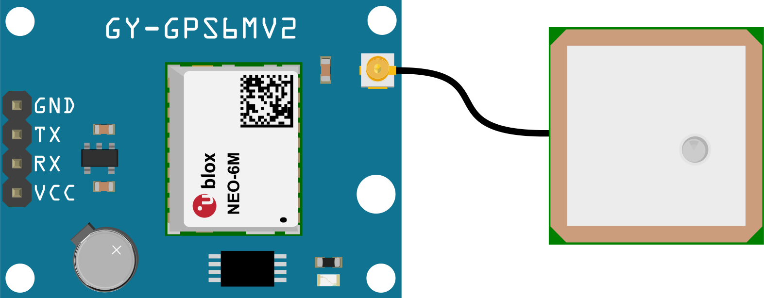
 Design with NEO-6M GPS Module with EPROM in Cirkit Designer
Introduction
The NEO-6M GPS Module is a compact and reliable GPS receiver designed to provide accurate positioning and timing data. It features an integrated EPROM, which allows the module to store configuration settings and firmware, ensuring consistent performance across power cycles. This module is widely used in navigation, location tracking, and timing applications due to its high sensitivity, low power consumption, and ease of integration.
Explore Projects Built with NEO-6M GPS Module with EPROM
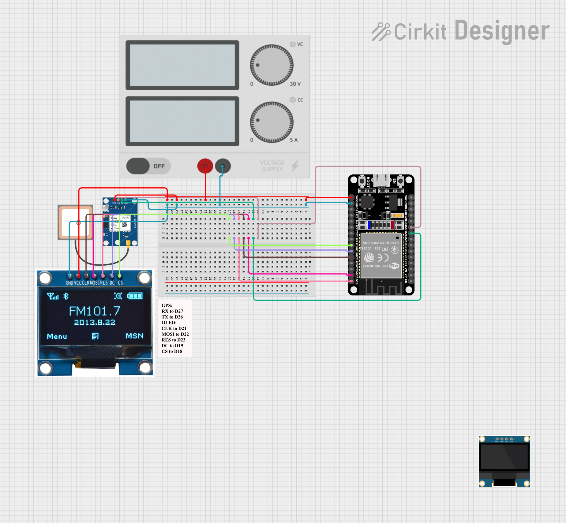 Open Project in Cirkit Designer
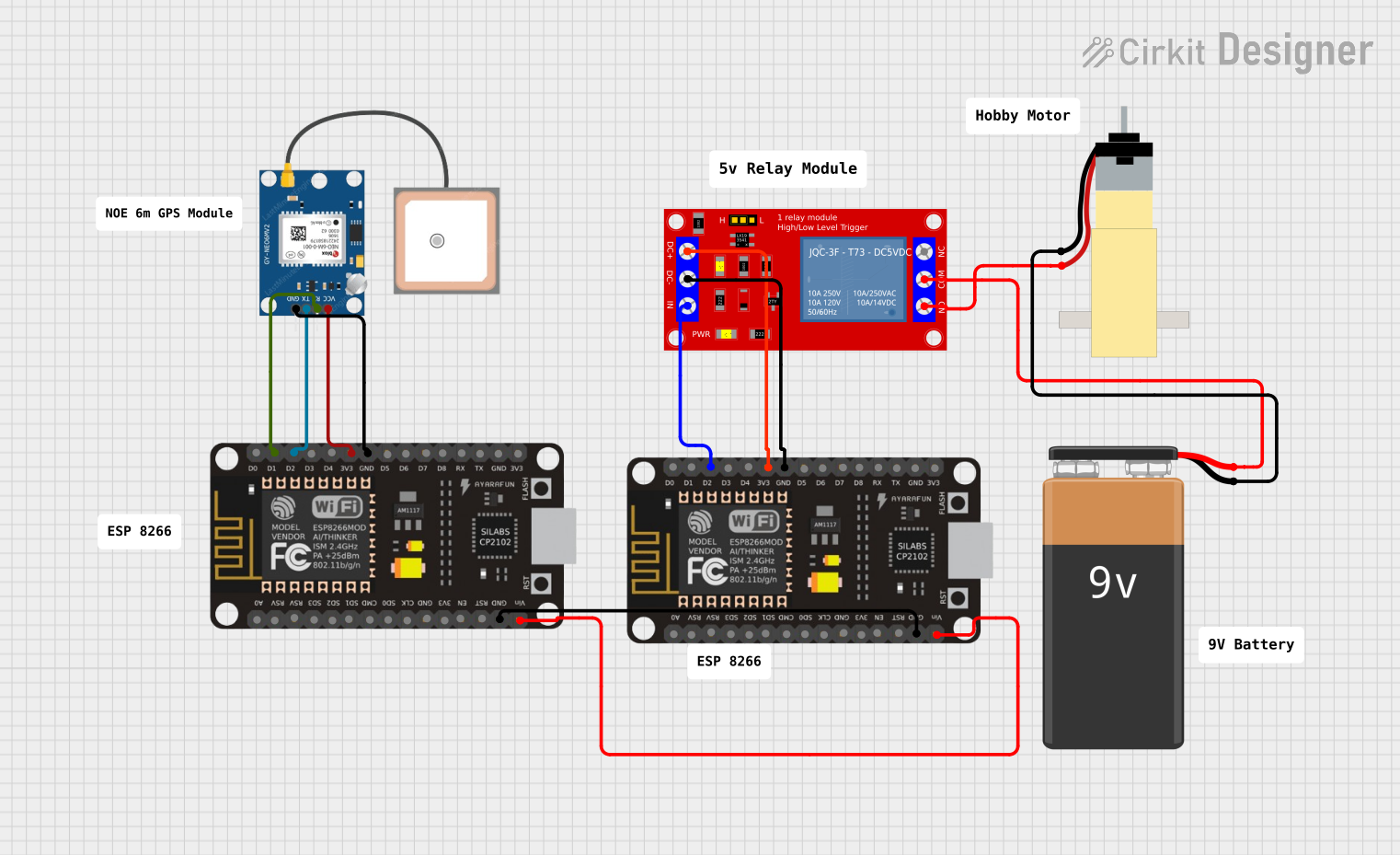 Open Project in Cirkit Designer
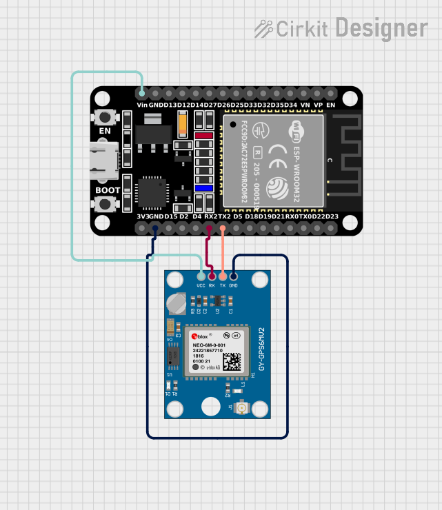 Open Project in Cirkit Designer
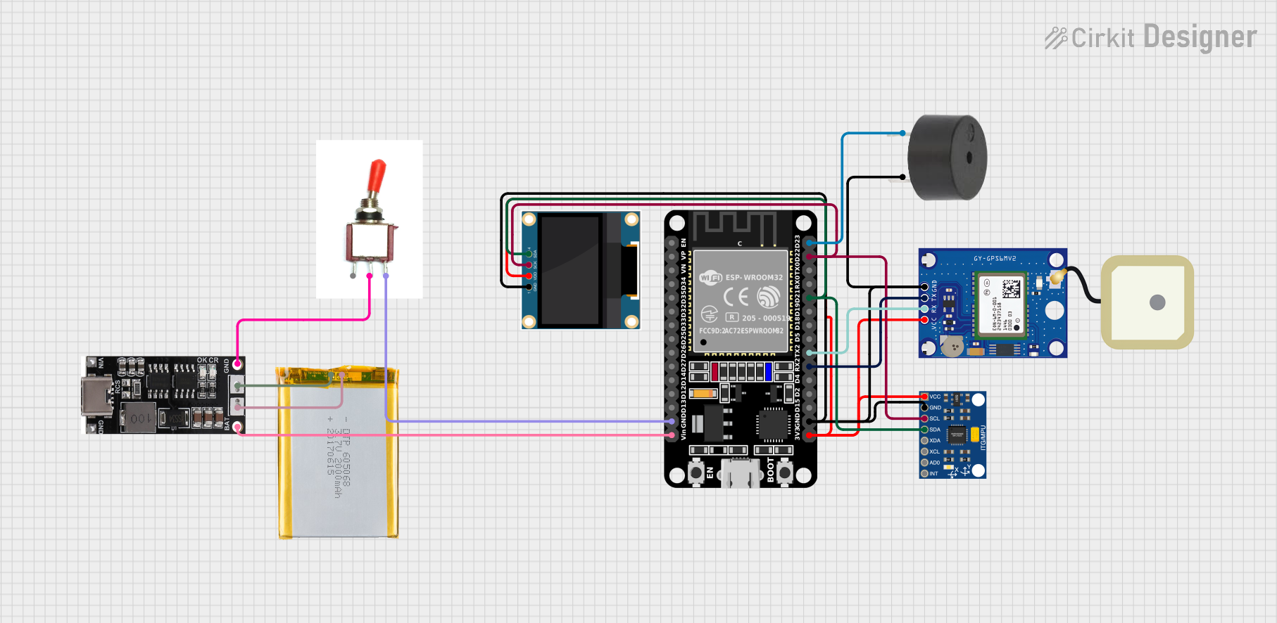 Open Project in Cirkit Designer
Explore Projects Built with NEO-6M GPS Module with EPROM
Open Project in Cirkit DesignerOpen Project in Cirkit DesignerOpen Project in Cirkit DesignerOpen Project in Cirkit DesignerCommon Applications:
- Vehicle navigation systems
- Drone and UAV positioning
- Personal tracking devices
- IoT applications requiring geolocation
- Timing synchronization for networks and systems
Technical Specifications
Key Technical Details:
| Parameter | Specification |
|---|---|
| GPS Receiver Type | u-blox NEO-6M |
| Frequency | L1 (1575.42 MHz) |
| Position Accuracy | 2.5 meters CEP (Circular Error Probable) |
| Velocity Accuracy | 0.1 m/s |
| Time Accuracy | 30 ns |
| Cold Start Time | 27 seconds |
| Warm Start Time | 1 second |
| Hot Start Time | < 1 second |
| Sensitivity | -161 dBm (tracking), -147 dBm (cold start) |
| Operating Voltage | 3.3V to 5V |
| Operating Current | 45 mA (typical) |
| Communication Interface | UART (default baud rate: 9600 bps) |
| Antenna | External active antenna (included) |
| EPROM | Integrated for configuration storage |
Pin Configuration:
| Pin Name | Pin Number | Description |
|---|---|---|
| VCC | 1 | Power supply input (3.3V to 5V) |
| GND | 2 | Ground |
| TX | 3 | UART Transmit (data output) |
| RX | 4 | UART Receive (data input) |
| PPS | 5 | Pulse Per Second (timing signal output) |
Usage Instructions
How to Use the NEO-6M GPS Module in a Circuit:
- Power Supply: Connect the
VCCpin to a 3.3V or 5V power source and theGNDpin to ground. - UART Communication: Connect the
TXpin of the module to the RX pin of your microcontroller (e.g., Arduino UNO) and theRXpin of the module to the TX pin of the microcontroller. - Antenna Connection: Attach the included active antenna to the module's antenna port for optimal signal reception.
- Data Reading: Use a UART interface to read NMEA (National Marine Electronics Association) sentences from the module. These sentences contain GPS data such as latitude, longitude, altitude, and time.
Important Considerations:
- Antenna Placement: Ensure the antenna has a clear view of the sky for optimal satellite reception. Avoid placing it near metal objects or inside enclosures that block signals.
- Baud Rate: The default UART baud rate is 9600 bps. If needed, you can configure the baud rate using u-blox's u-center software.
- Power Stability: Use a stable power supply to avoid performance issues or data loss.
- EEPROM Configuration: The integrated EPROM stores settings, so any changes made to the configuration will persist after power cycles.
Example Code for Arduino UNO:
#include <SoftwareSerial.h>

// Define RX and TX pins for SoftwareSerial
SoftwareSerial gpsSerial(4, 3); // RX = Pin 4, TX = Pin 3

void setup() {
  Serial.begin(9600); // Initialize Serial Monitor at 9600 bps
  gpsSerial.begin(9600); // Initialize GPS module at 9600 bps

  Serial.println("NEO-6M GPS Module Test");
}

void loop() {
  // Check if data is available from the GPS module
  while (gpsSerial.available()) {
    char c = gpsSerial.read(); // Read one character from GPS module
    Serial.print(c); // Print the character to Serial Monitor

    // NMEA sentences will be displayed in the Serial Monitor
    // Example: $GPGGA,123456.00,3723.2475,N,12158.3416,W,1,08,0.9,545.4,M,46.9,M,,*47
  }
}
Notes:
- Connect the GPS module's
TXpin to Arduino'sRXpin (pin 4 in the code) and theRXpin to Arduino'sTXpin (pin 3 in the code). - Open the Serial Monitor to view the NMEA sentences output by the GPS module.
Troubleshooting and FAQs
Common Issues and Solutions:
No GPS Fix (No Satellite Data):
- Ensure the antenna has a clear view of the sky.
- Wait for a few minutes for the module to acquire satellite signals, especially during the first use (cold start).
- Check the power supply for stability.
No Data Output:
- Verify the UART connections (TX and RX pins).
- Ensure the baud rate of the GPS module matches the baud rate in your code (default: 9600 bps).
- Check if the module is powered correctly.
Inconsistent Data:
- Ensure the antenna is not obstructed or placed near interference sources.
- Use a stable power source to avoid voltage fluctuations.
EEPROM Configuration Not Saved:
- Use u-blox's u-center software to configure and save settings to the EPROM.
FAQs:
Q: Can the NEO-6M GPS Module work indoors?
A: The module may work indoors near windows, but performance will be significantly reduced. For best results, use it outdoors with a clear view of the sky.Q: How many satellites does the module need for a fix?
A: The module requires at least 4 satellites for a 3D fix (latitude, longitude, and altitude).Q: Can I change the default baud rate?
A: Yes, you can use u-blox's u-center software to configure the baud rate and other settings.Q: What is the purpose of the PPS pin?
A: The PPS (Pulse Per Second) pin outputs a precise timing signal that can be used for synchronization in timing-critical applications.
By following this documentation, you can effectively integrate and use the NEO-6M GPS Module in your projects.