Cirkit Designer Logo
Cirkit Designer
Your all-in-one circuit design IDE
Home / 
Component Documentation

How to Use Push Pull Solenoid: Examples, Pinouts, and Specs

Image of Push Pull Solenoid
Cirkit Designer LogoDesign with Push Pull Solenoid in Cirkit Designer

Introduction

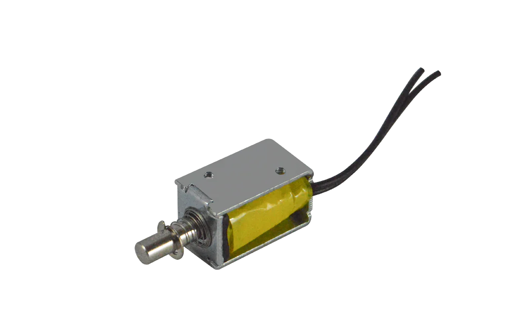
A push-pull solenoid is an electromechanical device designed to convert electrical energy into linear motion. It is widely used in various applications such as vending machines, locking mechanisms, robotics, and industrial equipment. The solenoid can either push or pull an object, depending on the polarity of the current applied to its coil, making it a versatile component for motion control systems.

Explore Projects Built with Push Pull Solenoid

Use Cirkit Designer to design, explore, and prototype these projects online. Some projects support real-time simulation. Click "Open Project" to start designing instantly!
Arduino-Controlled Multi-Solenoid Actuation System
Image of GP: A project utilizing Push Pull Solenoid in a practical application
This circuit is designed to control multiple push-pull solenoids using an Arduino UNO. Each solenoid is switched by a pMOS transistor, with a flyback diode for protection against inductive spikes. The Arduino's digital output pins are used to operate the transistors, but the control code for the Arduino is not yet provided.
Cirkit Designer LogoOpen Project in Cirkit Designer
Arduino Mega 2560-Based Dual Solenoid Control System with Pushbutton Activation
Image of mcrobot: A project utilizing Push Pull Solenoid in a practical application
This circuit uses an Arduino Mega 2560 to control two 12V single-channel relays, which in turn control two solenoids. A pushbutton and a resistor are used to provide input to the Arduino, and a LiPo battery supplies power to the solenoids through the relays.
Cirkit Designer LogoOpen Project in Cirkit Designer
ESP32-Controlled Pneumatic Solenoid Valve with MOSFET Switching
Image of ESPooky32: A project utilizing Push Pull Solenoid in a practical application
This circuit uses an ESP32 microcontroller to control a 12V pneumatic solenoid valve via an IRFZ44N MOSFET as a switch. The ESP32 outputs a control signal through a 220-ohm resistor to the gate of the MOSFET, which in turn controls the power to the solenoid valve from a 12V power supply. A 10k-ohm resistor provides a pull-down for the MOSFET gate to ensure it remains off when not driven by the ESP32.
Cirkit Designer LogoOpen Project in Cirkit Designer
Battery-Powered IR Sensor Controlled Water Pump System
Image of Copy of SEM project: A project utilizing Push Pull Solenoid in a practical application
This circuit is designed to control a water pump and solenoid valve using an IR sensor and a relay. The IR sensor triggers a PNP transistor, which in turn activates the relay to power the water pump and solenoid valve from a separate battery source.
Cirkit Designer LogoOpen Project in Cirkit Designer

Explore Projects Built with Push Pull Solenoid

Use Cirkit Designer to design, explore, and prototype these projects online. Some projects support real-time simulation. Click "Open Project" to start designing instantly!
Image of GP: A project utilizing Push Pull Solenoid in a practical application
Arduino-Controlled Multi-Solenoid Actuation System
This circuit is designed to control multiple push-pull solenoids using an Arduino UNO. Each solenoid is switched by a pMOS transistor, with a flyback diode for protection against inductive spikes. The Arduino's digital output pins are used to operate the transistors, but the control code for the Arduino is not yet provided.
Cirkit Designer LogoOpen Project in Cirkit Designer
Image of mcrobot: A project utilizing Push Pull Solenoid in a practical application
Arduino Mega 2560-Based Dual Solenoid Control System with Pushbutton Activation
This circuit uses an Arduino Mega 2560 to control two 12V single-channel relays, which in turn control two solenoids. A pushbutton and a resistor are used to provide input to the Arduino, and a LiPo battery supplies power to the solenoids through the relays.
Cirkit Designer LogoOpen Project in Cirkit Designer
Image of ESPooky32: A project utilizing Push Pull Solenoid in a practical application
ESP32-Controlled Pneumatic Solenoid Valve with MOSFET Switching
This circuit uses an ESP32 microcontroller to control a 12V pneumatic solenoid valve via an IRFZ44N MOSFET as a switch. The ESP32 outputs a control signal through a 220-ohm resistor to the gate of the MOSFET, which in turn controls the power to the solenoid valve from a 12V power supply. A 10k-ohm resistor provides a pull-down for the MOSFET gate to ensure it remains off when not driven by the ESP32.
Cirkit Designer LogoOpen Project in Cirkit Designer
Image of Copy of SEM project: A project utilizing Push Pull Solenoid in a practical application
Battery-Powered IR Sensor Controlled Water Pump System
This circuit is designed to control a water pump and solenoid valve using an IR sensor and a relay. The IR sensor triggers a PNP transistor, which in turn activates the relay to power the water pump and solenoid valve from a separate battery source.
Cirkit Designer LogoOpen Project in Cirkit Designer

Technical Specifications

General Characteristics

  • Type: Push-Pull Solenoid
  • Operation Mode: Intermittent
  • Life Expectancy: Typically rated for several million cycles

Electrical Ratings

  • Rated Voltage: 12V DC (commonly available)
  • Current Draw: Varies with model (e.g., 1A at 12V DC)
  • Power Consumption: Depends on current draw (e.g., 12W at 12V/1A)

Mechanical Ratings

  • Stroke Length: Varies with model (e.g., 10mm)
  • Force: Depends on design and voltage (e.g., 5N at 12V)

Pin Configuration and Descriptions

Pin Number Description
1 Coil Positive (+)
2 Coil Negative (-)

Usage Instructions

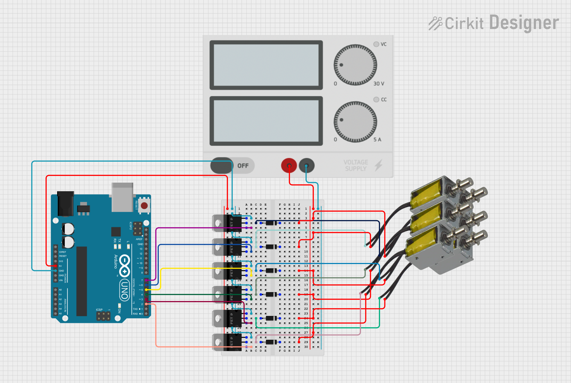
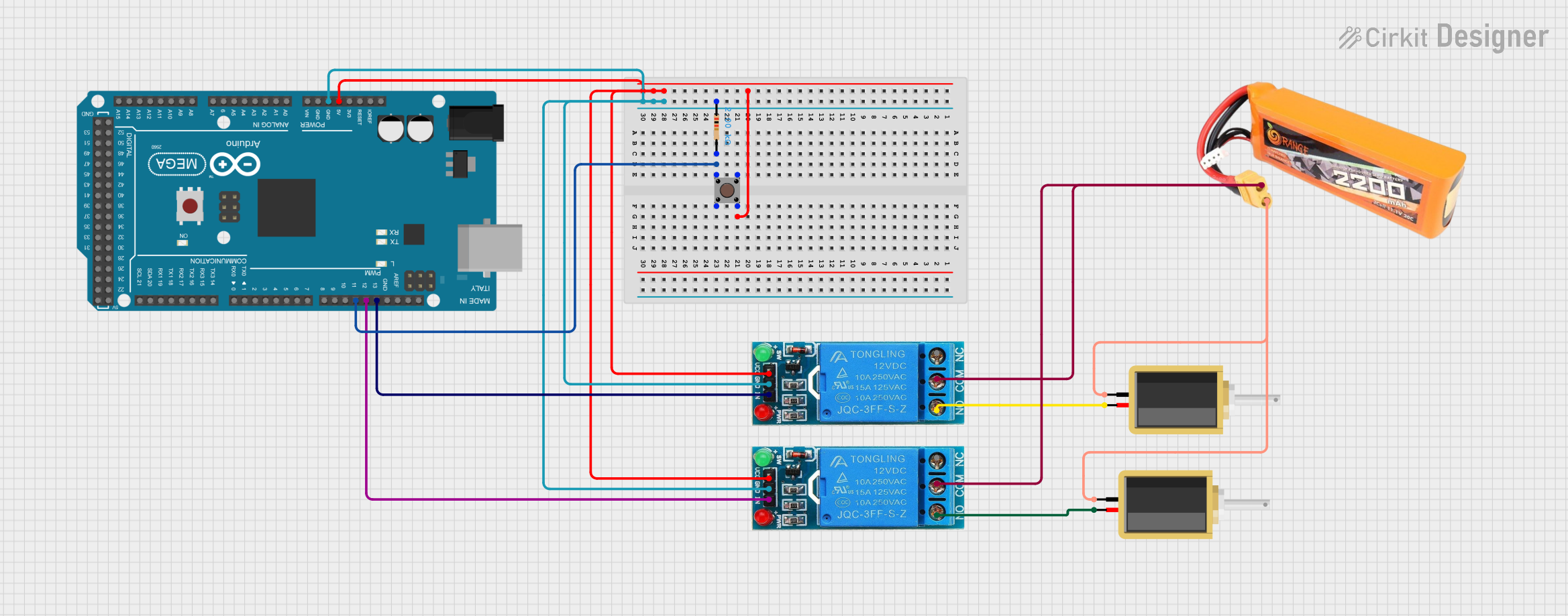
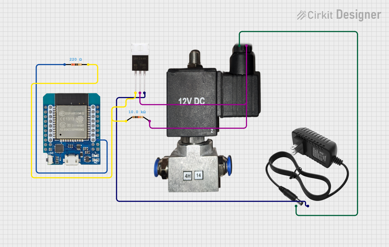
Integration into a Circuit

  1. Power Supply: Ensure that the power supply matches the voltage rating of the solenoid.
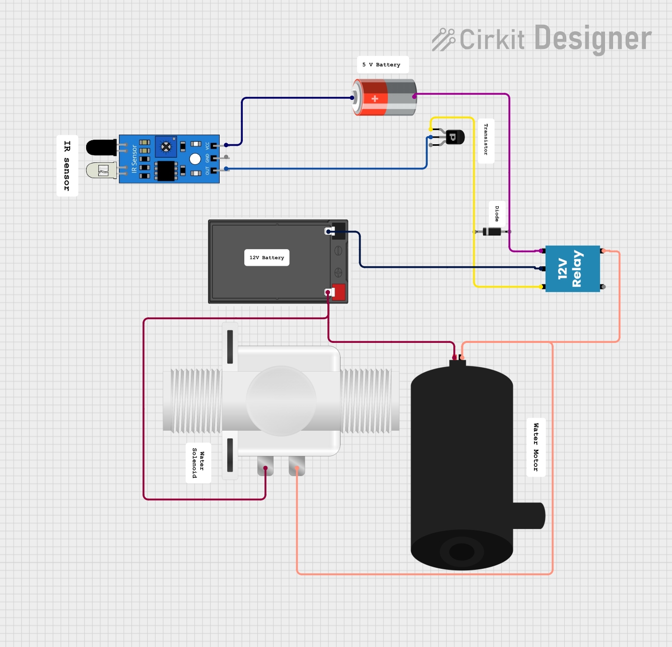
  2. Driving Circuit: Use a transistor, relay, or MOSFET to control the high current required by the solenoid.
  3. Diode: Place a flyback diode across the solenoid coil to protect the driving circuit from voltage spikes.

Best Practices

  • Duty Cycle: Adhere to the recommended duty cycle to prevent overheating.
  • Mounting: Secure the solenoid firmly to prevent movement and noise.
  • Activation Time: Limit the activation time to the manufacturer's specifications.

Example Arduino UNO Code

// Define the solenoid control pin
const int solenoidPin = 7;

void setup() {
  // Set the solenoid pin as an output
  pinMode(solenoidPin, OUTPUT);
}

void loop() {
  // Activate the solenoid
  digitalWrite(solenoidPin, HIGH);
  delay(1000); // Keep the solenoid activated for 1 second

  // Deactivate the solenoid
  digitalWrite(solenoidPin, LOW);
  delay(1000); // Wait for 1 second before next cycle
}

Troubleshooting and FAQs

Common Issues

  • Solenoid Does Not Actuate: Check power supply and connections.
  • Overheating: Ensure proper duty cycle and activation time.
  • Weak Force: Verify that the voltage matches the solenoid's rating.

FAQs

Q: Can I operate the solenoid with a different voltage? A: Operating the solenoid outside its rated voltage can damage the component or affect performance.

Q: How can I reverse the motion of the solenoid? A: Reversing the polarity will not reverse the motion. Push-pull solenoids are designed to push or pull depending on the mechanical configuration, not the electrical polarity.

Q: What is the purpose of the flyback diode? A: The diode protects the driving circuit from voltage spikes generated when the solenoid is turned off.

This documentation provides a comprehensive guide to using a push-pull solenoid. For specific models, always refer to the manufacturer's datasheet for precise ratings and instructions.