
How to Use OSCILLATOR: Examples, Pinouts, and Specs
 Design with OSCILLATOR in Cirkit Designer
Introduction
An oscillator is an electronic component or circuit that generates a repetitive, oscillating signal, typically in the form of a sine wave, square wave, or other periodic waveform. Oscillators are essential in a wide range of applications, including generating clock signals for digital circuits, producing audio frequencies in sound systems, and serving as the basis for radio frequency (RF) communication systems.
Explore Projects Built with OSCILLATOR
 Open Project in Cirkit Designer
 Open Project in Cirkit Designer
 Open Project in Cirkit Designer
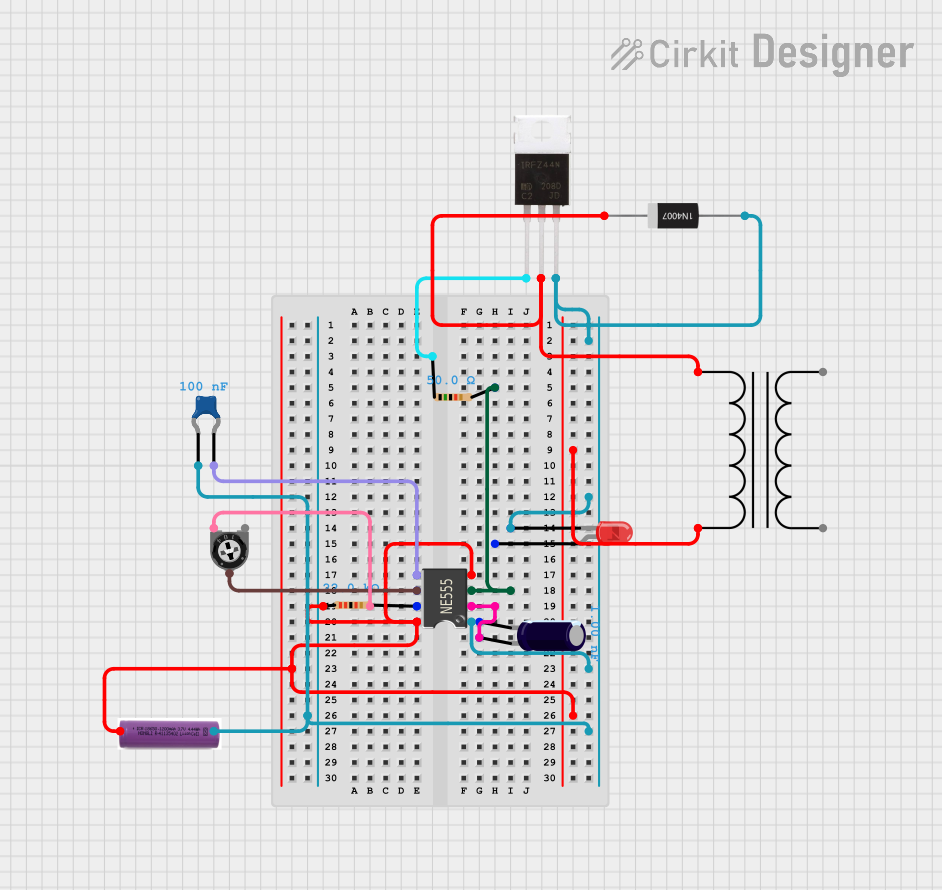 Open Project in Cirkit Designer
Explore Projects Built with OSCILLATOR
Open Project in Cirkit DesignerOpen Project in Cirkit DesignerOpen Project in Cirkit DesignerOpen Project in Cirkit DesignerCommon Applications and Use Cases
- Clock generation: Provides timing signals for microcontrollers, processors, and digital circuits.
- Audio signal generation: Produces tones and frequencies for audio equipment and synthesizers.
- RF communication: Generates carrier signals for wireless communication systems.
- Test equipment: Used in signal generators and oscilloscopes for testing and debugging circuits.
Technical Specifications
Oscillators come in various types, such as crystal oscillators, RC oscillators, and LC oscillators. Below are the general technical specifications for a typical crystal oscillator:
Key Technical Details
- Frequency Range: 1 kHz to 100 MHz (varies by type and model)
- Supply Voltage: 3.3V to 5V (common for digital circuits)
- Output Waveform: Sine wave, square wave, or triangular wave
- Stability: ±10 ppm to ±50 ppm (frequency stability depends on the crystal)
- Operating Temperature: -40°C to +85°C (varies by model)
- Load Capacitance: 10 pF to 30 pF (for crystal oscillators)
Pin Configuration and Descriptions
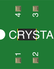
Below is a typical pinout for a 4-pin crystal oscillator:
| Pin Number | Pin Name | Description |
|---|---|---|
| 1 | VCC | Power supply input (3.3V or 5V) |
| 2 | GND | Ground connection |
| 3 | Output | Oscillator signal output (square or sine wave) |
| 4 | NC/Enable | No connection or enable pin (varies by model) |
Usage Instructions
How to Use the Oscillator in a Circuit
- Power Supply: Connect the VCC pin to a stable power source (e.g., 3.3V or 5V) and the GND pin to the circuit ground.
- Signal Output: Connect the output pin to the circuit where the oscillating signal is required. For example, connect it to the clock input of a microcontroller.
- Load Capacitance: If using a crystal oscillator, ensure the load capacitance matches the specifications of the crystal for optimal performance.
- Enable Pin: If the oscillator has an enable pin, ensure it is connected to the appropriate logic level (e.g., HIGH to enable, LOW to disable).
Important Considerations and Best Practices
- Decoupling Capacitors: Place decoupling capacitors (e.g., 0.1 µF) near the VCC pin to reduce noise and ensure stable operation.
- PCB Layout: Minimize trace lengths between the oscillator and the circuit it drives to reduce signal degradation.
- Frequency Stability: Use temperature-compensated or oven-controlled oscillators for applications requiring high frequency stability.
- Avoid Overloading: Ensure the connected circuit does not exceed the oscillator's output drive capability.
Example: Using an Oscillator with Arduino UNO
Below is an example of connecting an external oscillator to an Arduino UNO to provide a clock signal:
// Example: Using an external oscillator with Arduino UNO
// Connect the oscillator output to pin 8 of the Arduino UNO

void setup() {
  pinMode(8, INPUT); // Set pin 8 as input to receive the clock signal
  Serial.begin(9600); // Initialize serial communication
}

void loop() {
  // Read the clock signal from the oscillator
  int clockSignal = digitalRead(8);

  // Print the clock signal state to the Serial Monitor
  Serial.print("Clock Signal: ");
  Serial.println(clockSignal);

  delay(100); // Add a small delay for readability
}
Troubleshooting and FAQs
Common Issues and Solutions
No Output Signal:
- Cause: Incorrect power supply or loose connections.
- Solution: Verify the VCC and GND connections and ensure the power supply voltage matches the oscillator's specifications.
Unstable Frequency:
- Cause: Mismatched load capacitance or excessive noise.
- Solution: Use the correct load capacitors and add decoupling capacitors near the power pins.
Signal Distortion:
- Cause: Long PCB traces or improper termination.
- Solution: Shorten the trace length and use proper impedance matching techniques.
Oscillator Not Starting:
- Cause: Insufficient drive level or incorrect enable pin state.
- Solution: Check the enable pin logic level and ensure the connected circuit does not overload the oscillator.
FAQs
Q: Can I use an oscillator with a different frequency than specified in my circuit?
A: It depends on the circuit requirements. Ensure the new frequency is compatible with the components and does not disrupt timing-sensitive operations.Q: How do I choose between a crystal oscillator and an RC oscillator?
A: Crystal oscillators offer higher frequency stability and precision, while RC oscillators are simpler and more cost-effective for less critical applications.Q: Can I connect multiple devices to the same oscillator output?
A: Yes, but ensure the total load does not exceed the oscillator's drive capability. Use a buffer if necessary.
This documentation provides a comprehensive guide to understanding and using oscillators effectively in electronic circuits.