How to Use joenoes: Examples, Pinouts, and Specs
Introduction
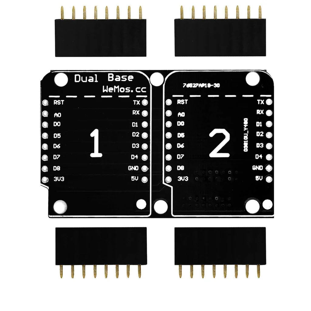
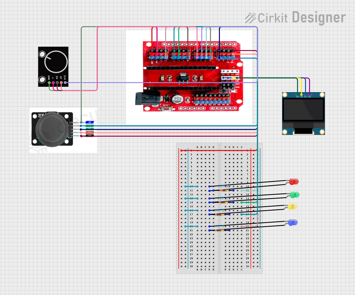
The Joenoes Expansion Shield is a state-of-the-art electronic component designed by WEMOS for advanced superconducting applications. This shield is typically used to enhance the capabilities of microcontroller platforms such as the Arduino UNO, providing an interface for superconducting modules and components. Its primary use cases include quantum computing interfaces, cryogenic temperature monitoring, and high-speed data acquisition systems in research and development environments.
Explore Projects Built with joenoes
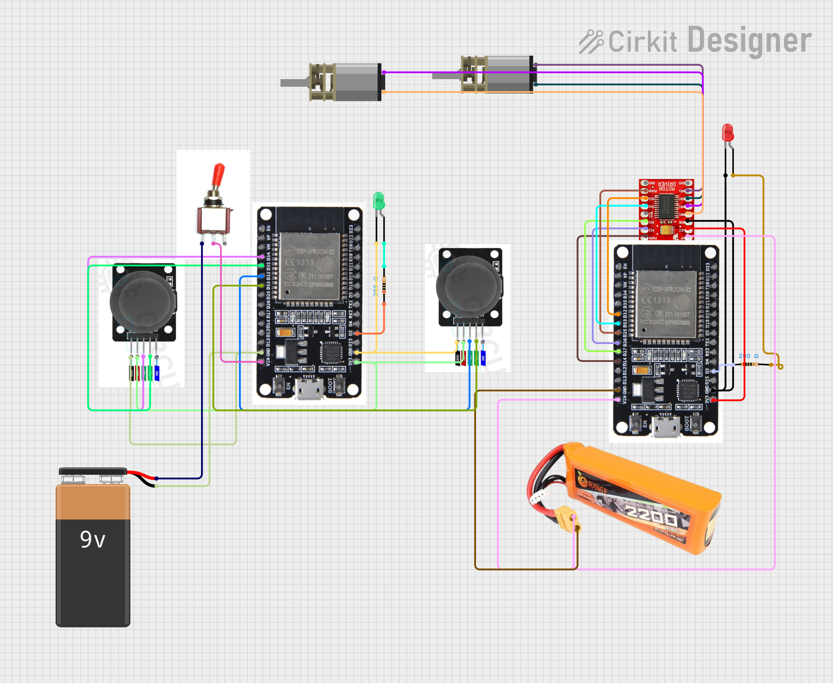
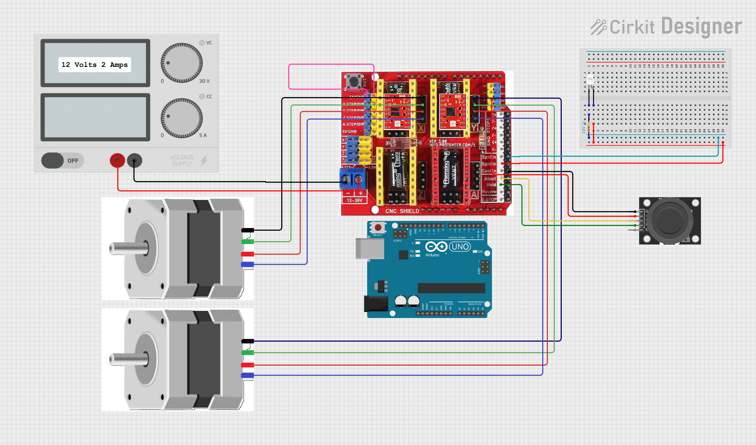
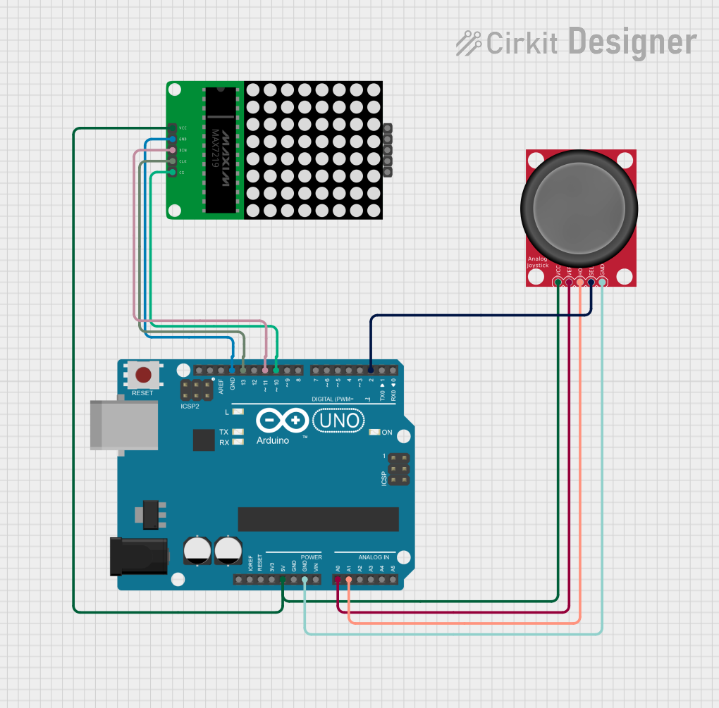
Explore Projects Built with joenoes
Technical Specifications
General Specifications
- Operating Voltage: 3.3V
- Superconducting Threshold: Below 9K (-264.15°C)
- Maximum Current: 500mA
- Communication: I2C, SPI, UART
- Dimensions: 68.6mm x 53.4mm
Pin Configuration and Descriptions
| Pin Number | Description | Voltage/Signal | Notes |
|---|---|---|---|
| 1 | VCC | 3.3V | Power supply |
| 2 | GND | Ground | Ground connection |
| 3 | SDA | I2C Data | I2C communication line |
| 4 | SCL | I2C Clock | I2C communication clock |
| 5 | MISO | SPI Data Out | SPI Master In Slave Out |
| 6 | MOSI | SPI Data In | SPI Master Out Slave In |
| 7 | SCK | SPI Clock | SPI Clock signal |
| 8 | SS | SPI Select | SPI Slave Select |
| 9 | RX | UART Receive | UART receive data |
| 10 | TX | UART Transmit | UART transmit data |
| 11-20 | General Purpose I/O (GPIO) | Digital I/O | Configurable digital pins |
| 21-22 | Analog Inputs (A0, A1) | Analog Signal | Analog sensor inputs |
Usage Instructions
Integration with Arduino UNO
- Power Off: Ensure that the Arduino UNO is powered off before connecting the Joenoes Expansion Shield.
- Mounting: Carefully align the shield's pins with the Arduino's headers and press down gently to seat the shield.
- Power On: Once the shield is securely in place, power on the Arduino UNO.
- Programming: Use the Arduino IDE to upload your code to the Arduino UNO with the shield attached.
Best Practices
- Always handle the shield with care to avoid static discharge or physical damage to the pins.
- Ensure proper cooling when operating near the superconducting threshold to maintain performance.
- Use shielded cables for all connections to minimize interference in sensitive superconducting applications.
Example Code for Arduino UNO
#include <Wire.h> // Include the I2C library (required for the shield)

void setup() {
  Wire.begin(); // Initialize I2C communication
  Serial.begin(9600); // Start serial communication at 9600 baud rate

  // Initialize the Joenoes Expansion Shield (fictional initialization)
  initJoenoesShield();
}

void loop() {
  // Code to interact with the shield's features
  // For example, reading a superconducting sensor
  int sensorValue = readSuperconductingSensor();
  Serial.println(sensorValue); // Output the sensor value to the serial monitor

  delay(1000); // Wait for 1 second before reading the sensor again
}

// Function to initialize the Joenoes Expansion Shield
void initJoenoesShield() {
  // Code to initialize the shield (fictional example)
}

// Function to read a value from a superconducting sensor
int readSuperconductingSensor() {
  // Code to read and return the sensor value (fictional example)
  return 42; // Placeholder for an actual sensor reading
}
Troubleshooting and FAQs
Common Issues
- Shield Not Recognized: Ensure that the shield is properly seated on the Arduino UNO. Check for any bent pins or loose connections.
- Communication Errors: Verify that the correct communication protocol (I2C, SPI, UART) is being used in your code. Check the wiring and connections for continuity and proper shielding.
- Unexpected Sensor Readings: Ensure that the sensor is operating within the specified temperature range for superconducting applications. Check for environmental interference or damage to the sensor.
FAQs
Q: Can the Joenoes Expansion Shield operate at room temperature? A: While the shield can function at room temperature, its superconducting features are only active below 9K.
Q: Is additional cooling required for the shield? A: Yes, when operating near the superconducting threshold, appropriate cryogenic cooling methods should be employed.
Q: How do I update the firmware on the Joenoes Expansion Shield? A: Firmware updates, if available, can be applied through the Arduino IDE using a USB connection to the Arduino UNO.
For further assistance, please contact WEMOS support or refer to the community forums dedicated to the Joenoes Expansion Shield.