How to Use PS2: Examples, Pinouts, and Specs

Introduction
The PS/2 connector, manufactured by Arduino (Part ID: Connector), is a 6-pin mini-DIN connector used primarily for connecting keyboards and mice to computers. This connector was widely used in the 1990s and early 2000s before being largely replaced by USB interfaces. Despite its decline in mainstream use, the PS/2 connector remains relevant in certain applications, such as legacy systems, industrial equipment, and specific embedded systems.
Explore Projects Built with PS2

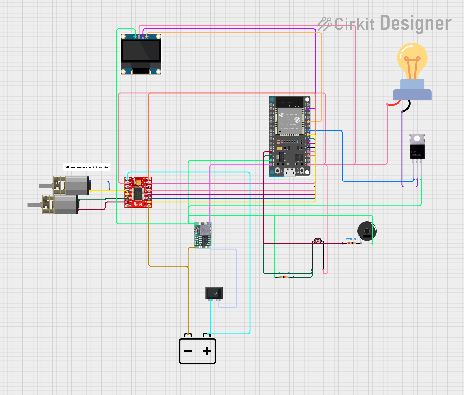
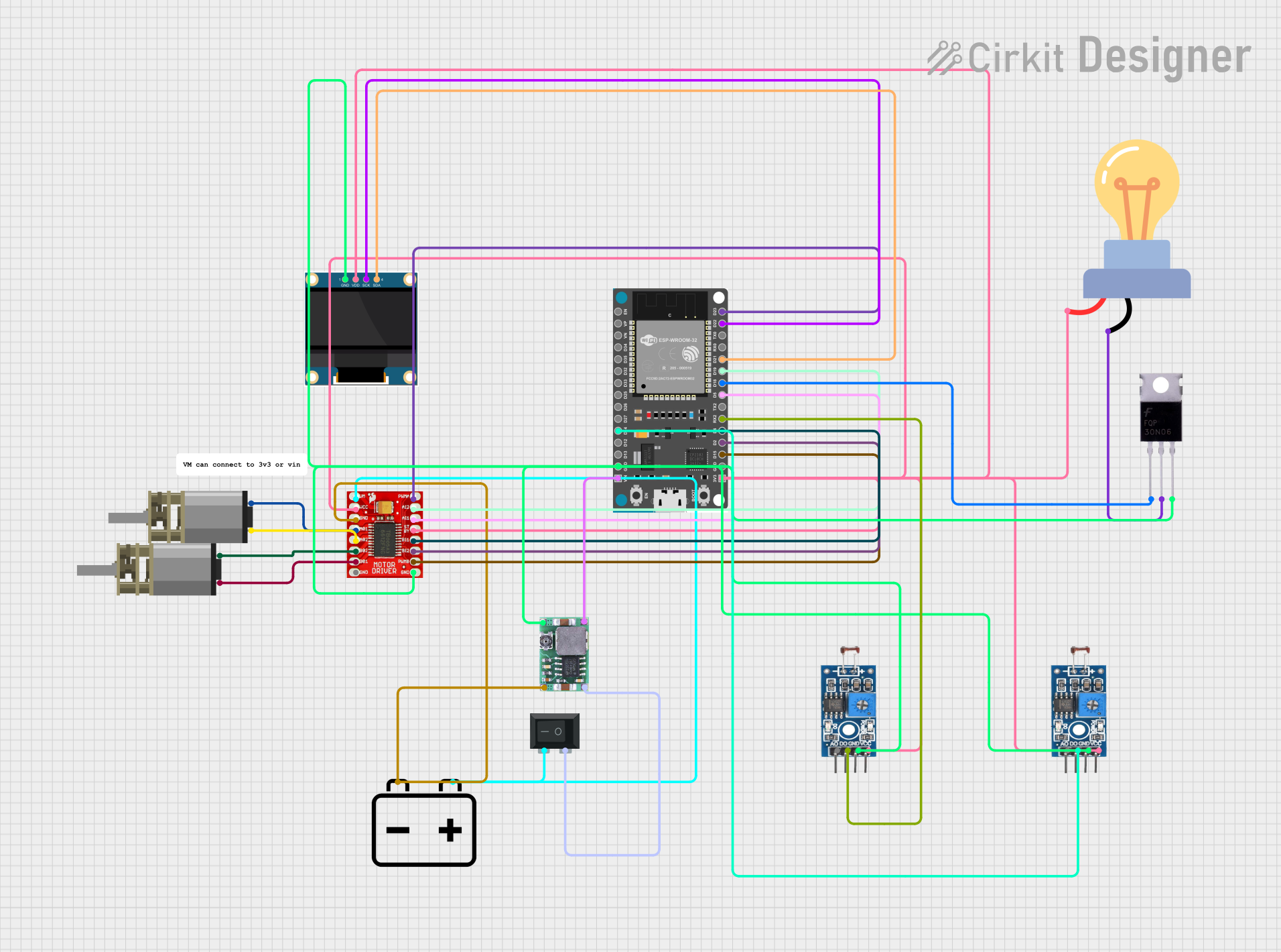

Explore Projects Built with PS2
Common Applications and Use Cases
- Legacy Computer Systems: Connecting older keyboards and mice to computers.
- Embedded Systems: Used in microcontroller projects for interfacing with PS/2 devices.
- Industrial Equipment: Employed in machinery that requires robust and reliable input devices.
- Hobbyist Projects: Ideal for DIY electronics projects involving retro hardware.
Technical Specifications
Key Technical Details
| Parameter | Value |
|---|---|
| Voltage | 5V DC |
| Current | 275 mA (maximum) |
| Power Rating | 1.375 W (maximum) |
| Connector Type | 6-pin mini-DIN |
| Manufacturer | Arduino |
| Part ID | Connector |
Pin Configuration and Descriptions
| Pin Number | Name | Description |
|---|---|---|
| 1 | Data | Serial data line |
| 2 | Not Used | Not connected |
| 3 | Ground | Ground |
| 4 | Vcc | +5V power supply |
| 5 | Clock | Clock signal |
| 6 | Not Used | Not connected |
Usage Instructions
How to Use the PS/2 Connector in a Circuit
- Power Supply: Connect Pin 4 (Vcc) to a 5V power source and Pin 3 (Ground) to the ground of your circuit.
- Data and Clock Lines: Connect Pin 1 (Data) and Pin 5 (Clock) to the corresponding data and clock lines of your microcontroller or interface device.
- Unused Pins: Pins 2 and 6 are not used and can be left unconnected.
Important Considerations and Best Practices
- Voltage Levels: Ensure that the voltage levels are within the specified range (5V) to avoid damaging the PS/2 device.
- Signal Integrity: Use short and shielded cables to maintain signal integrity, especially in noisy environments.
- Pull-up Resistors: Consider using pull-up resistors on the data and clock lines to ensure proper signal levels.
Example: Connecting to an Arduino UNO
To connect a PS/2 keyboard to an Arduino UNO, you can use the following example code:
#include <PS2Keyboard.h>

// Define the clock and data pins
const int DataPin = 8;
const int ClockPin = 9;

PS2Keyboard keyboard;

void setup() {
  Serial.begin(9600);
  keyboard.begin(DataPin, ClockPin);
  Serial.println("Keyboard Test:");
}

void loop() {
  if (keyboard.available()) {
    char c = keyboard.read();
    // Print the character to the serial monitor
    Serial.print(c);
  }
}
Troubleshooting and FAQs
Common Issues and Solutions
No Response from PS/2 Device:
- Solution: Check the power connections (Vcc and Ground) and ensure they are properly connected.
- Solution: Verify that the data and clock lines are correctly connected to the microcontroller.
Erratic Behavior or Missing Keystrokes:
- Solution: Use shorter and shielded cables to reduce noise and signal degradation.
- Solution: Add pull-up resistors to the data and clock lines if not already present.
Device Not Recognized:
- Solution: Ensure that the PS/2 device is compatible with the microcontroller or interface being used.
- Solution: Double-check the pin configuration and connections.
FAQs
Q: Can I use a PS/2 to USB adapter with this connector? A: Yes, you can use a PS/2 to USB adapter to connect PS/2 devices to USB ports, but ensure the adapter is compatible with your device.
Q: What is the maximum cable length for a PS/2 connection? A: The maximum recommended cable length for a PS/2 connection is approximately 6 feet (1.8 meters) to maintain signal integrity.
Q: Can I connect both a PS/2 keyboard and mouse to a single microcontroller? A: Yes, you can connect both a PS/2 keyboard and mouse to a single microcontroller, but you will need separate data and clock lines for each device.
This documentation provides a comprehensive overview of the PS/2 connector, including its technical specifications, usage instructions, and troubleshooting tips. Whether you are a beginner or an experienced user, this guide will help you effectively utilize the PS/2 connector in your projects.