How to Use BH1750FVI: Examples, Pinouts, and Specs
Introduction
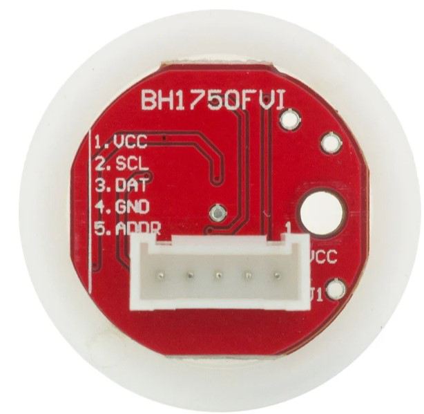
The Light Intensity Module Ball is a device designed to measure and control the intensity of light in a circuit. It is equipped with a light sensor that detects ambient light levels and outputs a corresponding signal, which can be used for monitoring or controlling light-dependent systems. This module is commonly used in applications such as photography for exposure control, horticulture for optimizing plant growth, and environmental monitoring to track light conditions.
Explore Projects Built with BH1750FVI
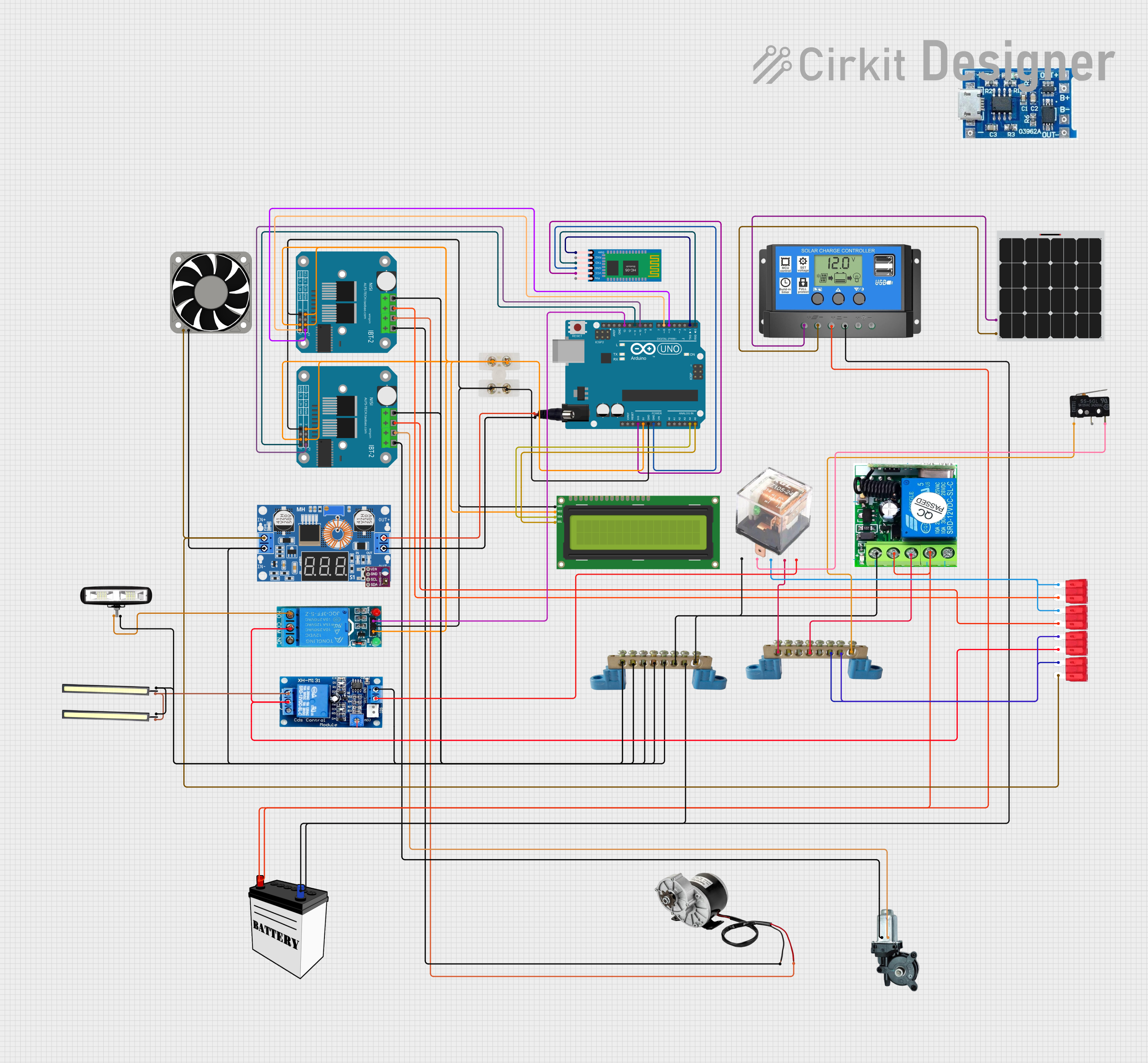
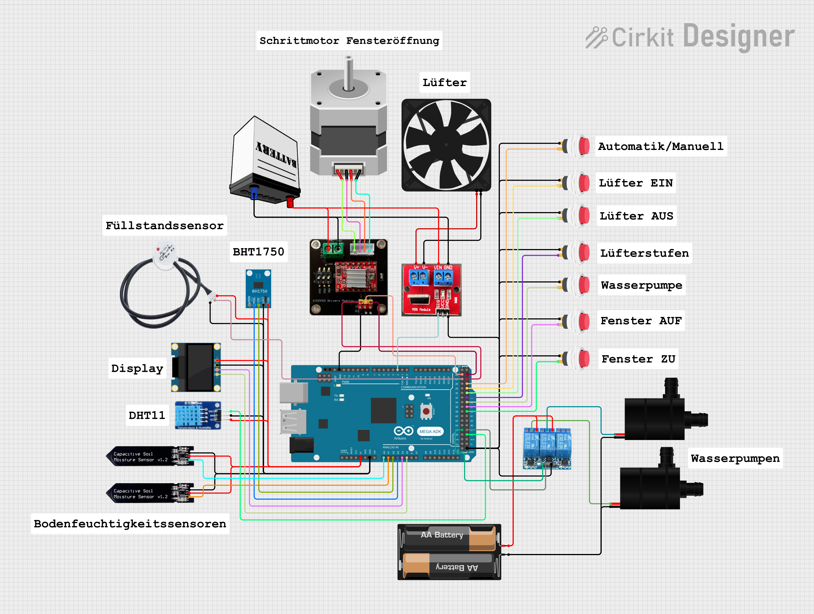
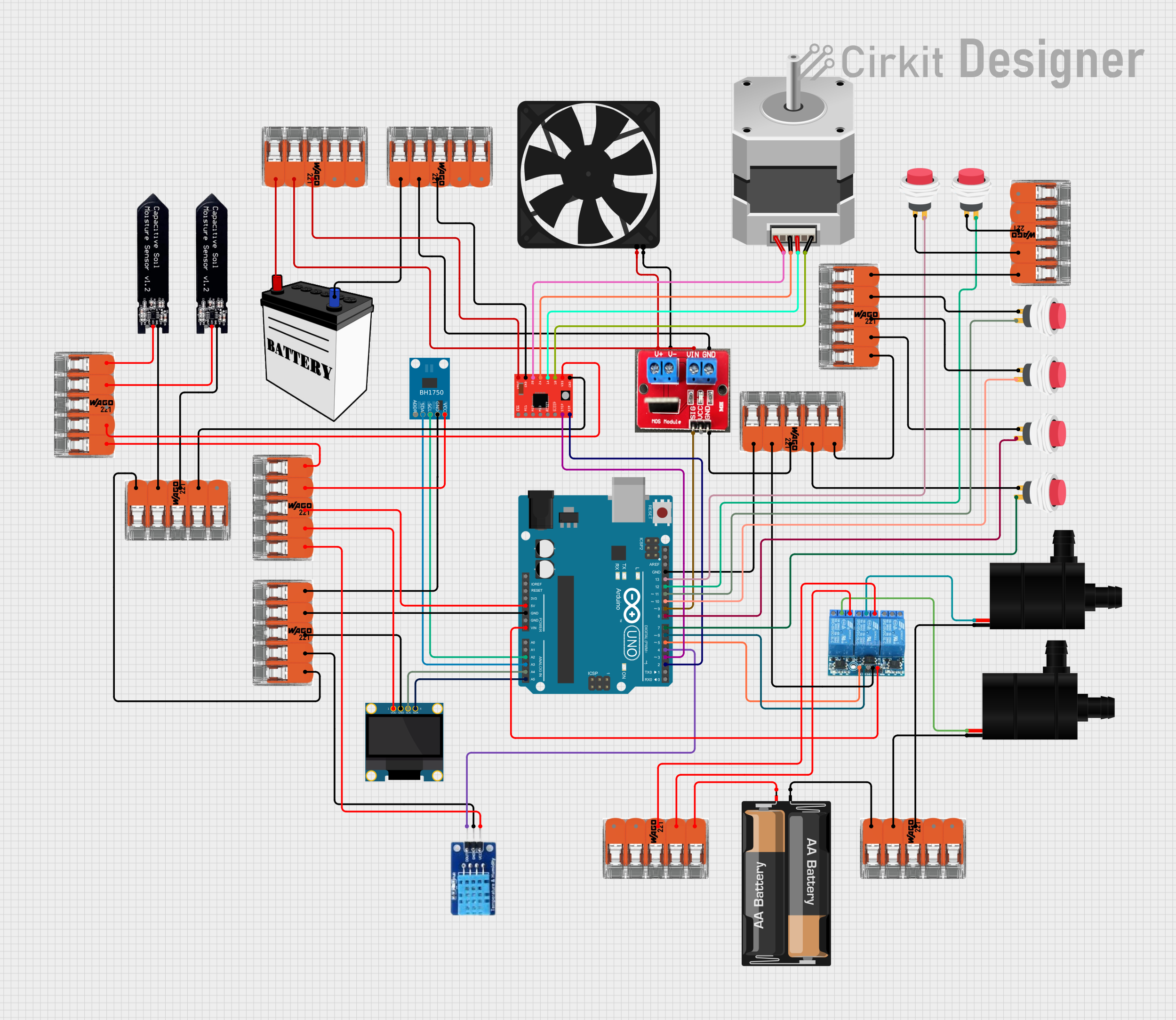
Explore Projects Built with BH1750FVI
Technical Specifications
- Operating Voltage: 3.3V to 5V DC
- Output Type: Analog and Digital
- Light Sensitivity Range: 0 to 100,000 lux
- Response Time: < 1 ms
- Operating Temperature: -20°C to 70°C
- Dimensions: 30mm x 20mm x 10mm
Pin Configuration and Descriptions
| Pin Name | Type | Description |
|---|---|---|
| VCC | Power Input | Connect to a 3.3V or 5V DC power supply. |
| GND | Ground | Connect to the ground of the circuit. |
| AO | Analog Output | Outputs an analog voltage proportional to the detected light intensity. |
| DO | Digital Output | Outputs a HIGH or LOW signal based on the light intensity threshold (adjustable). |
Usage Instructions
How to Use the Component in a Circuit
Power the Module:
Connect theVCCpin to a 3.3V or 5V power source and theGNDpin to the ground of your circuit.Choose Output Type:
- Use the
AOpin if you need an analog signal to measure the exact light intensity. - Use the
DOpin if you need a digital signal to detect whether the light intensity is above or below a threshold.
- Use the
Adjust the Threshold:
The module includes a potentiometer to set the light intensity threshold for the digital output. Rotate the potentiometer clockwise or counterclockwise to adjust the sensitivity.Connect to a Microcontroller (Optional):
If using an Arduino UNO, connect theAOpin to an analog input pin (e.g., A0) or theDOpin to a digital input pin (e.g., D2).
Important Considerations and Best Practices
- Avoid exposing the module to extreme temperatures or humidity, as this may affect its performance.
- Ensure the module is not directly exposed to water or other liquids.
- When using the analog output, consider adding a capacitor to smooth out any noise in the signal.
- For accurate measurements, avoid placing the module in areas with reflective surfaces that may distort light readings.
Example Code for Arduino UNO
The following code demonstrates how to read both the analog and digital outputs of the Light Intensity Module Ball using an Arduino UNO:
// Define pin connections
const int analogPin = A0; // Connect AO pin to A0 on Arduino
const int digitalPin = 2; // Connect DO pin to D2 on Arduino

void setup() {
  Serial.begin(9600); // Initialize serial communication at 9600 baud
  pinMode(digitalPin, INPUT); // Set digital pin as input
}

void loop() {
  // Read the analog value from the AO pin
  int lightLevel = analogRead(analogPin);

  // Read the digital value from the DO pin
  int lightThreshold = digitalRead(digitalPin);

  // Print the analog light intensity value
  Serial.print("Light Intensity (Analog): ");
  Serial.println(lightLevel);

  // Print the digital threshold status
  if (lightThreshold == HIGH) {
    Serial.println("Light intensity is above the threshold.");
  } else {
    Serial.println("Light intensity is below the threshold.");
  }

  delay(500); // Wait for 500ms before the next reading
}
Troubleshooting and FAQs
Common Issues Users Might Face
No Output Signal:
- Cause: Incorrect wiring or insufficient power supply.
- Solution: Double-check all connections and ensure the power supply is within the operating voltage range.
Inaccurate Readings:
- Cause: Interference from reflective surfaces or electrical noise.
- Solution: Place the module in a stable environment and consider adding a capacitor to the analog output.
Digital Output Not Triggering:
- Cause: Threshold not properly set.
- Solution: Adjust the potentiometer to set the desired light intensity threshold.
Module Overheating:
- Cause: Operating outside the recommended voltage range.
- Solution: Ensure the input voltage is between 3.3V and 5V.
FAQs
Q: Can this module be used outdoors?
A: Yes, but it should be protected from direct exposure to water or extreme weather conditions.
Q: What is the difference between the analog and digital outputs?
A: The analog output provides a continuous voltage proportional to the light intensity, while the digital output provides a HIGH or LOW signal based on the set threshold.
Q: How do I calibrate the module for specific light conditions?
A: Use the onboard potentiometer to adjust the threshold for the digital output. For analog output, you can calibrate in software by mapping the sensor's range to your desired scale.
Q: Can this module detect infrared light?
A: No, this module is designed to detect visible light and may not respond to infrared wavelengths.