
How to Use COMPUTER-PERIPHERAL-POWER: Examples, Pinouts, and Specs

 Design with COMPUTER-PERIPHERAL-POWER in Cirkit Designer
Introduction
The COMPUTER-PERIPHERAL-POWER is a power supply unit specifically designed to provide stable and reliable electrical power to computer peripherals such as external hard drives, printers, monitors, and USB hubs. This component ensures that peripherals operate efficiently without power interruptions or fluctuations, which can lead to performance issues or hardware damage.
Explore Projects Built with COMPUTER-PERIPHERAL-POWER
 Open Project in Cirkit Designer
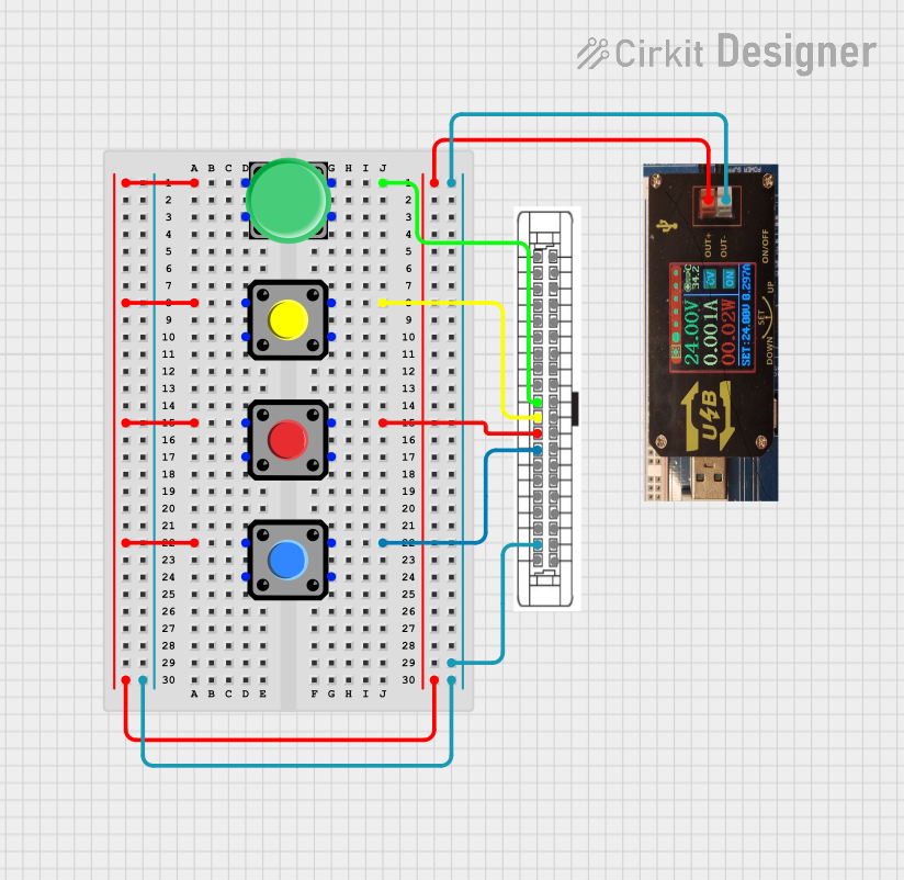 Open Project in Cirkit Designer
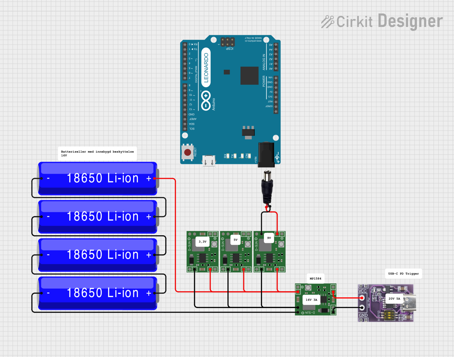 Open Project in Cirkit Designer
 Open Project in Cirkit Designer
Explore Projects Built with COMPUTER-PERIPHERAL-POWER
Open Project in Cirkit DesignerOpen Project in Cirkit DesignerOpen Project in Cirkit DesignerOpen Project in Cirkit DesignerCommon Applications and Use Cases
- Powering external hard drives and SSD enclosures
- Supplying power to USB hubs and charging stations
- Supporting printers, scanners, and other office peripherals
- Providing power to monitors and small form-factor devices
- Ensuring stable operation of IoT devices connected to computers
Technical Specifications
The COMPUTER-PERIPHERAL-POWER unit is designed to meet the power requirements of a wide range of peripherals. Below are the key technical details:
General Specifications
| Parameter | Value |
|---|---|
| Input Voltage Range | 100-240V AC, 50/60Hz |
| Output Voltage Options | 5V DC, 12V DC |
| Maximum Output Current | 5A (5V), 3A (12V) |
| Power Output Rating | 25W (5V), 36W (12V) |
| Efficiency | ≥85% |
| Operating Temperature | 0°C to 40°C |
| Storage Temperature | -20°C to 70°C |
| Safety Certifications | CE, FCC, RoHS |
Pin Configuration and Descriptions
The output connector of the COMPUTER-PERIPHERAL-POWER unit typically uses a barrel jack or USB Type-A/Type-C connector. Below is the pin configuration for the barrel jack and USB Type-A connectors:
Barrel Jack Connector
| Pin Name | Description |
|---|---|
| Center | Positive Voltage (V+) |
| Outer | Ground (GND) |
USB Type-A Connector
| Pin Name | Description |
|---|---|
| VBUS | Positive Voltage (5V DC) |
| D- | Data Line (-) |
| D+ | Data Line (+) |
| GND | Ground |
Usage Instructions
How to Use the Component in a Circuit
- Determine the Voltage and Current Requirements: Verify the voltage and current requirements of the peripheral device you intend to power. Ensure the COMPUTER-PERIPHERAL-POWER unit provides the appropriate output voltage (e.g., 5V or 12V) and sufficient current.
- Connect the Output:
- For barrel jack connectors, ensure the polarity matches the device's input requirements (center positive or center negative).
- For USB-powered devices, connect the USB Type-A or Type-C cable to the peripheral.
- Plug in the Power Supply: Connect the COMPUTER-PERIPHERAL-POWER unit to an AC power outlet using the provided power cord.
- Power On the Peripheral: Turn on the peripheral device and verify that it operates correctly.
Important Considerations and Best Practices
- Check Compatibility: Always confirm that the voltage and current ratings of the power supply match the requirements of the peripheral device.
- Avoid Overloading: Do not connect devices that exceed the maximum current rating of the power supply.
- Use Proper Cables: Ensure that the cables used are of high quality and capable of handling the required current without significant voltage drop.
- Ventilation: Place the power supply in a well-ventilated area to prevent overheating.
- Safety Precautions: Avoid exposing the power supply to moisture or extreme temperatures.
Example: Using with an Arduino UNO
The COMPUTER-PERIPHERAL-POWER unit can be used to power an Arduino UNO via its barrel jack input. Below is an example code to blink an LED connected to the Arduino UNO:
// Example code to blink an LED using Arduino UNO
// Ensure the Arduino is powered using the COMPUTER-PERIPHERAL-POWER unit

const int ledPin = 13; // Pin connected to the onboard LED

void setup() {
  pinMode(ledPin, OUTPUT); // Set the LED pin as an output
}

void loop() {
  digitalWrite(ledPin, HIGH); // Turn the LED on
  delay(1000);               // Wait for 1 second
  digitalWrite(ledPin, LOW);  // Turn the LED off
  delay(1000);               // Wait for 1 second
}
Troubleshooting and FAQs
Common Issues Users Might Face
Peripheral Does Not Power On:
- Cause: Incorrect voltage or insufficient current.
- Solution: Verify the voltage and current requirements of the peripheral and ensure the power supply matches.
Overheating of the Power Supply:
- Cause: Overloading or poor ventilation.
- Solution: Reduce the load by disconnecting some devices or improve ventilation around the power supply.
Intermittent Power Loss:
- Cause: Loose connections or damaged cables.
- Solution: Check all connections and replace damaged cables.
Peripheral Malfunction:
- Cause: Incorrect polarity or incompatible power supply.
- Solution: Verify the polarity and compatibility of the power supply with the peripheral.
Solutions and Tips for Troubleshooting
- Use a multimeter to measure the output voltage of the power supply and ensure it matches the specifications.
- Inspect the connectors for signs of wear or damage.
- If the power supply fails to operate, check the fuse (if applicable) and replace it if blown.
- Refer to the user manual of the peripheral device for specific power requirements and recommendations.
By following this documentation, users can effectively utilize the COMPUTER-PERIPHERAL-POWER unit to power their computer peripherals safely and efficiently.