
How to Use BLDC Motor: Examples, Pinouts, and Specs
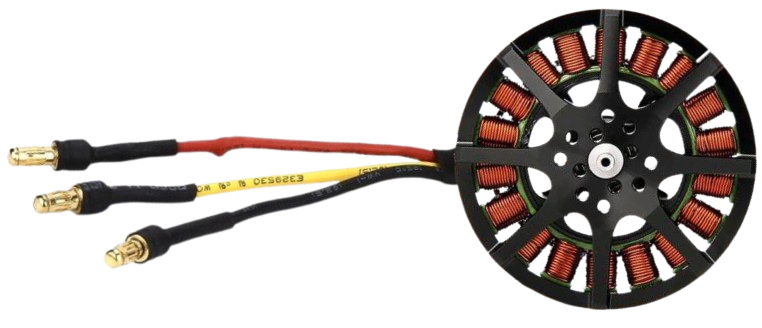
 Design with BLDC Motor in Cirkit Designer
Introduction
A Brushless DC (BLDC) Motor is an electric motor that operates without brushes, using electronic commutation instead. Unlike traditional brushed motors, BLDC motors rely on electronic controllers to switch the current in the motor windings, ensuring smooth and efficient operation. These motors are known for their high efficiency, reliability, and low maintenance, making them ideal for applications in robotics, electric vehicles, drones, HVAC systems, and various industrial machines.
Common applications of BLDC motors include:
- Electric vehicles (e.g., cars, scooters, and bicycles)
- Drones and unmanned aerial vehicles (UAVs)
- Robotics and automation systems
- Industrial machinery and conveyor belts
- HVAC systems (e.g., fans, blowers, and compressors)
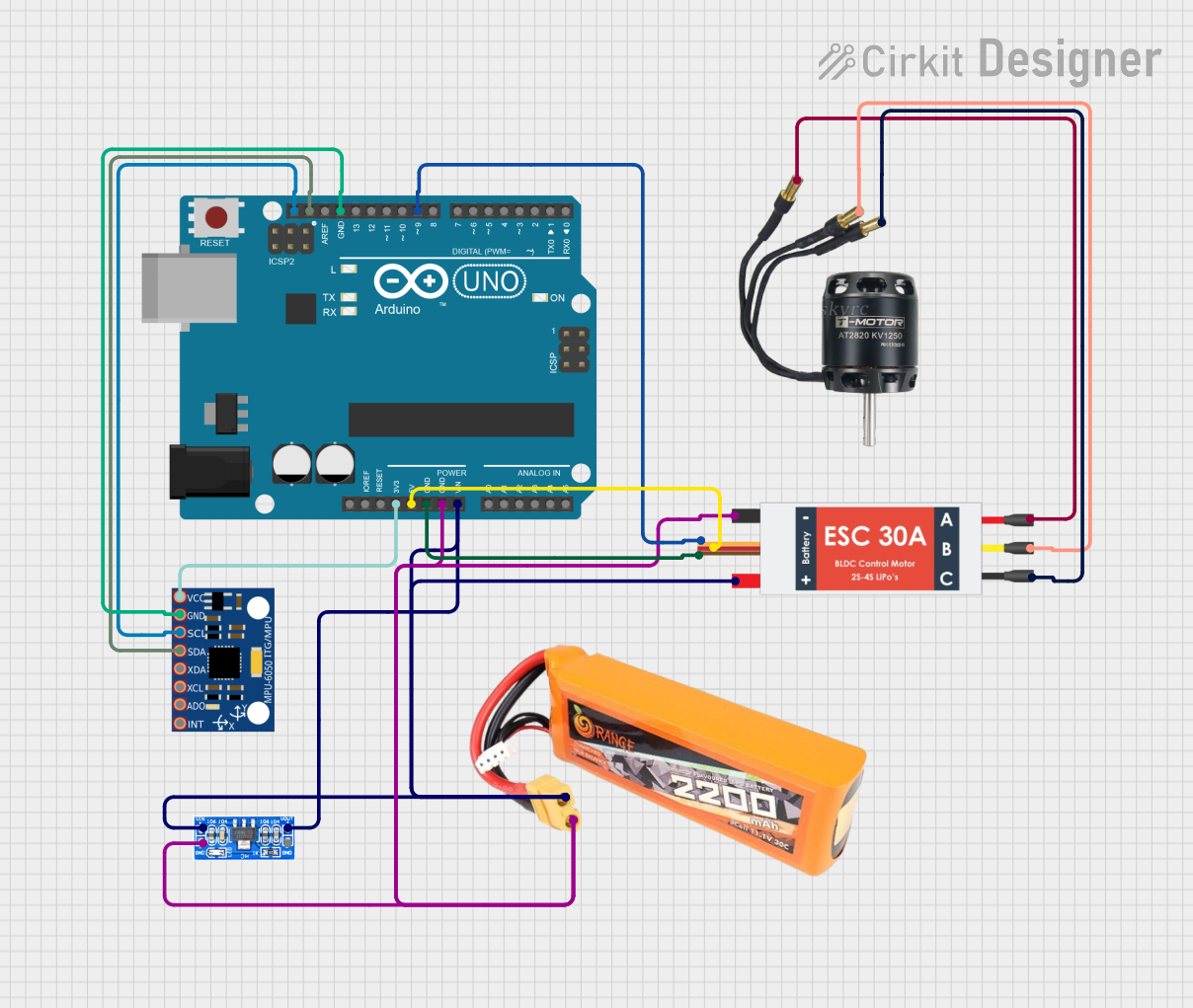
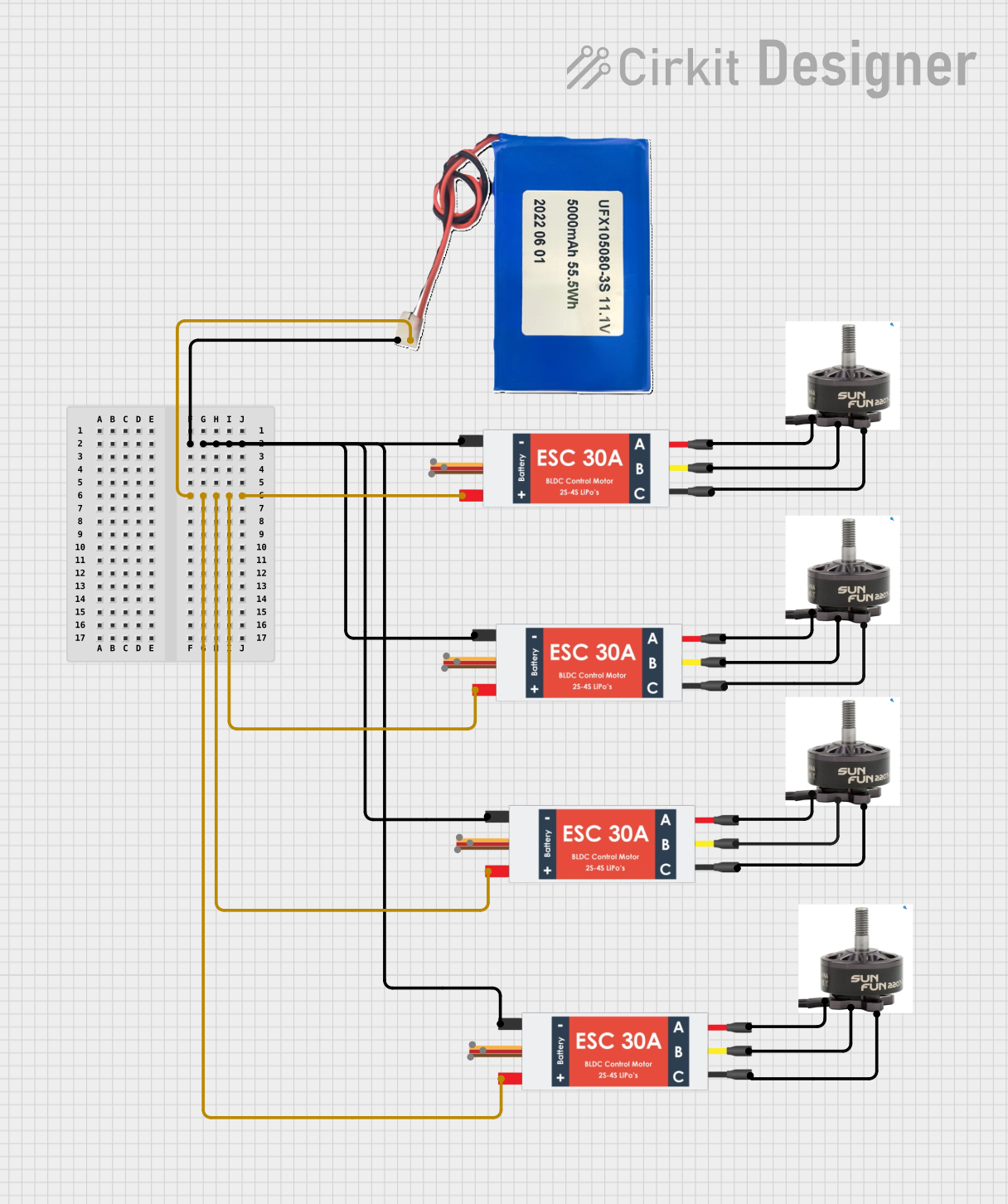
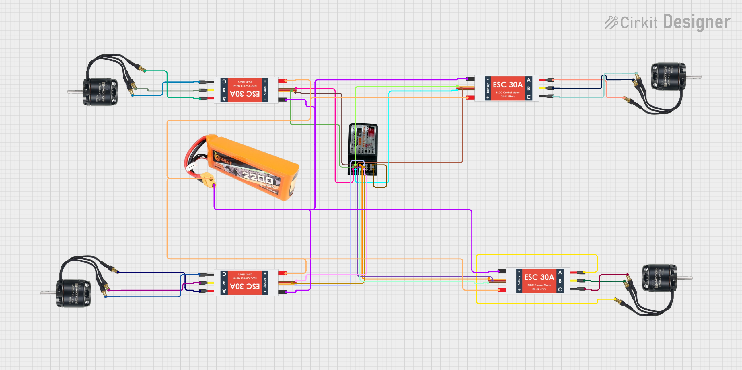
Explore Projects Built with BLDC Motor
 Open Project in Cirkit Designer
 Open Project in Cirkit Designer
 Open Project in Cirkit Designer
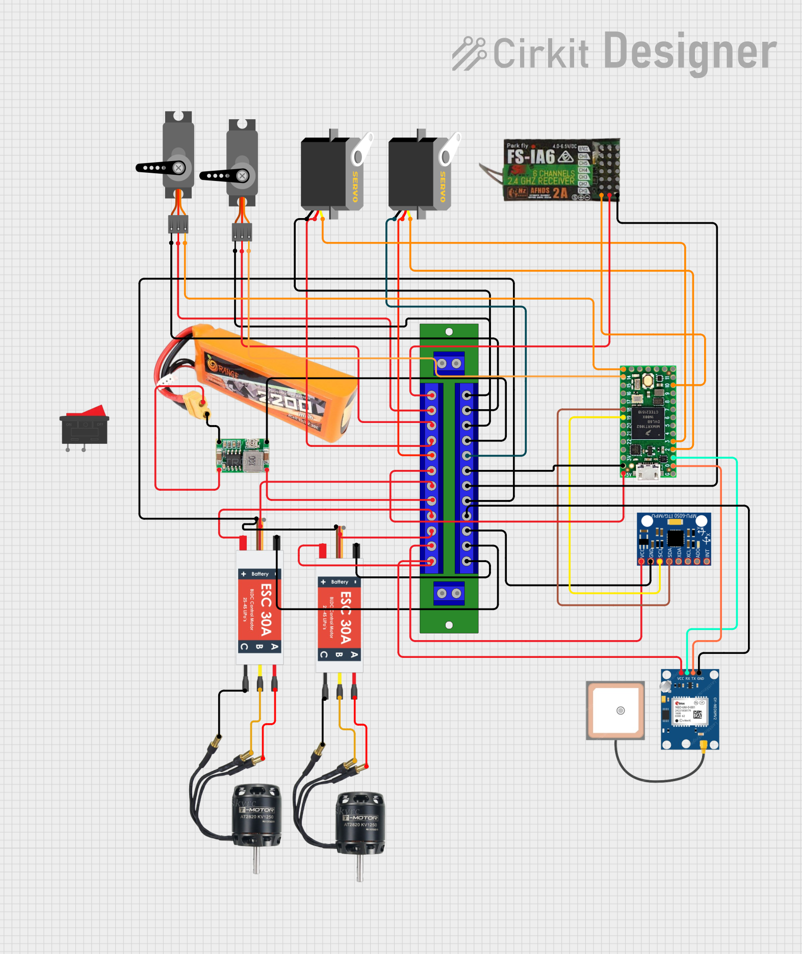 Open Project in Cirkit Designer
Explore Projects Built with BLDC Motor
Open Project in Cirkit DesignerOpen Project in Cirkit DesignerOpen Project in Cirkit DesignerOpen Project in Cirkit DesignerTechnical Specifications
Below are the general technical specifications for a typical BLDC motor. Note that specific values may vary depending on the motor model and manufacturer.
Key Technical Details
| Parameter | Description |
|---|---|
| Voltage Range | 6V to 48V (varies by model) |
| Rated Current | 1A to 50A (depending on application) |
| Power Output | 10W to several kW |
| Speed Range | 1,000 to 20,000 RPM |
| Number of Poles | 2 to 14 (varies by design) |
| Efficiency | Up to 95% |
| Commutation Type | Electronic (via controller) |
| Rotor Type | Permanent magnet |
| Operating Temperature | -20°C to 80°C |
Pin Configuration and Descriptions
BLDC motors typically have three main wires for the motor phases and additional wires for sensors (if applicable). Below is a general pin configuration:
Motor Phase Wires
| Wire Color | Function | Description |
|---|---|---|
| Red | Phase A | First motor winding |
| Yellow | Phase B | Second motor winding |
| Blue | Phase C | Third motor winding |
Hall Sensor Wires (if applicable)
| Wire Color | Function | Description |
|---|---|---|
| Black | Ground (GND) | Common ground for sensors |
| Red | VCC | Power supply for Hall sensors (5V) |
| Green | Hall Sensor A | Outputs signal for rotor position |
| White | Hall Sensor B | Outputs signal for rotor position |
| Yellow | Hall Sensor C | Outputs signal for rotor position |
Usage Instructions
How to Use the BLDC Motor in a Circuit
Connect the Motor to a BLDC Controller:
BLDC motors require an electronic speed controller (ESC) or a dedicated BLDC driver to operate. Connect the three motor phase wires (Red, Yellow, Blue) to the corresponding outputs on the controller.Power the Controller:
Provide the appropriate voltage and current to the BLDC controller based on the motor's specifications. Ensure the power supply can handle the peak current requirements.Connect Hall Sensors (if applicable):
If the motor has Hall sensors, connect the sensor wires to the controller. Ensure the VCC and GND connections are correct to avoid damaging the sensors.Control the Motor:
Use a microcontroller (e.g., Arduino UNO) or other control systems to send PWM signals to the BLDC controller. This will regulate the motor's speed and direction.
Important Considerations and Best Practices
- Match the Motor and Controller: Ensure the BLDC motor and controller are compatible in terms of voltage, current, and power ratings.
- Cooling: For high-power applications, ensure proper cooling to prevent overheating of the motor and controller.
- Startup Torque: BLDC motors may require a specific startup sequence to generate sufficient torque.
- Avoid Overloading: Do not exceed the motor's rated current or power to prevent damage.
- Secure Mounting: Properly mount the motor to avoid vibrations and ensure stable operation.
Example Code for Arduino UNO
Below is an example of how to control a BLDC motor using an Arduino UNO and an ESC:
// Example code to control a BLDC motor using an ESC and Arduino UNO
#include <Servo.h> // Include the Servo library to generate PWM signals

Servo esc; // Create a Servo object to control the ESC

void setup() {
  esc.attach(9); // Attach the ESC signal wire to pin 9 on the Arduino
  esc.writeMicroseconds(1000); // Send minimum throttle signal (1000 µs)
  delay(2000); // Wait for 2 seconds to initialize the ESC
}

void loop() {
  esc.writeMicroseconds(1500); // Set throttle to 50% (1500 µs)
  delay(5000); // Run the motor at 50% speed for 5 seconds

  esc.writeMicroseconds(1000); // Stop the motor (minimum throttle)
  delay(2000); // Wait for 2 seconds before restarting
}
Notes:
- Ensure the ESC is properly calibrated before running the motor.
- Adjust the
writeMicrosecondsvalues to control the motor speed (1000 µs = stop, 2000 µs = full speed).
Troubleshooting and FAQs
Common Issues and Solutions
Motor Does Not Spin:
- Check the power supply and ensure it meets the voltage and current requirements.
- Verify the connections between the motor, controller, and power source.
- Ensure the ESC is properly calibrated and receiving PWM signals.
Motor Vibrates or Spins Erratically:
- Check the phase wire connections; incorrect wiring can cause erratic behavior.
- Verify the Hall sensor connections (if applicable) and ensure they are functioning correctly.
- Ensure the controller's settings match the motor's specifications.
Motor Overheats:
- Reduce the load on the motor or lower the operating speed.
- Ensure proper ventilation or add a cooling system.
- Check for any mechanical obstructions or excessive friction.
No Response from ESC:
- Ensure the ESC is receiving a valid PWM signal from the microcontroller.
- Verify the ESC's power supply and connections.
FAQs
Q: Can I run a BLDC motor without a controller?
A: No, BLDC motors require an electronic controller to manage the commutation process. Running the motor without a controller is not possible.
Q: How do I reverse the direction of a BLDC motor?
A: To reverse the motor's direction, swap any two of the three phase wires (e.g., Red and Yellow).
Q: What is the advantage of using Hall sensors?
A: Hall sensors provide precise rotor position feedback, enabling smoother operation and better control, especially at low speeds.
Q: Can I use a BLDC motor with an Arduino?
A: Yes, you can use an Arduino to control a BLDC motor via an ESC. The Arduino generates PWM signals to regulate the motor's speed and direction.