How to Use Junction 3 in 12 out: Examples, Pinouts, and Specs
Introduction
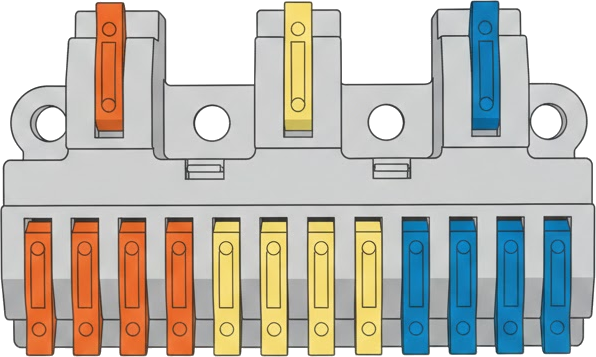
The Junction 3 in 12 out is a versatile electronic component designed to distribute signals from three input connections to twelve output connections. This component is commonly used in complex circuit designs where multiple signal paths need to be managed efficiently. It is ideal for applications such as signal routing, power distribution, and multi-channel communication systems.
Explore Projects Built with Junction 3 in 12 out


Explore Projects Built with Junction 3 in 12 out
Common Applications and Use Cases
- Signal distribution in audio and video systems
- Power splitting in low-power circuits
- Multi-channel communication systems
- Prototyping and testing of circuits with multiple outputs
- Industrial control systems requiring signal branching
Technical Specifications
The Junction 3 in 12 out is designed to handle a wide range of signals and is compatible with both analog and digital circuits. Below are the key technical details:
General Specifications
| Parameter | Value |
|---|---|
| Number of Inputs | 3 |
| Number of Outputs | 12 |
| Maximum Voltage Rating | 30V DC |
| Maximum Current Rating | 2A per output channel |
| Operating Temperature | -40°C to +85°C |
| Material | PCB with copper traces |
| Dimensions | 50mm x 50mm x 10mm |
Pin Configuration and Descriptions
The Junction 3 in 12 out has a total of 15 pins: 3 input pins and 12 output pins. The pin configuration is as follows:
Input Pins
| Pin Number | Label | Description |
|---|---|---|
| 1 | IN1 | Input signal 1 |
| 2 | IN2 | Input signal 2 |
| 3 | IN3 | Input signal 3 |
Output Pins
| Pin Number | Label | Description |
|---|---|---|
| 4 | OUT1 | Output signal from IN1 |
| 5 | OUT2 | Output signal from IN1 |
| 6 | OUT3 | Output signal from IN1 |
| 7 | OUT4 | Output signal from IN2 |
| 8 | OUT5 | Output signal from IN2 |
| 9 | OUT6 | Output signal from IN2 |
| 10 | OUT7 | Output signal from IN3 |
| 11 | OUT8 | Output signal from IN3 |
| 12 | OUT9 | Output signal from IN3 |
| 13 | OUT10 | Output signal from IN1 |
| 14 | OUT11 | Output signal from IN2 |
| 15 | OUT12 | Output signal from IN3 |
Usage Instructions
How to Use the Component in a Circuit
- Connect the Inputs: Attach the input signals to the IN1, IN2, and IN3 pins. Ensure the input voltage and current do not exceed the component's maximum ratings.
- Connect the Outputs: Distribute the output signals to the desired devices or circuits using the OUT1 to OUT12 pins.
- Power Considerations: If the component is used for power distribution, ensure the total current drawn by all outputs does not exceed the maximum current rating of 2A per channel.
- Signal Integrity: For high-frequency signals, use short and low-resistance connections to minimize signal degradation.
Important Considerations and Best Practices
- Avoid Overloading: Ensure the total current drawn by all outputs does not exceed the component's maximum current rating.
- Signal Isolation: If the input signals are from different sources, ensure proper isolation to prevent interference.
- Heat Management: In high-current applications, consider adding heat sinks or ensuring adequate ventilation to prevent overheating.
- Testing: Before connecting the component to a critical circuit, test it with a multimeter to verify continuity and proper signal distribution.
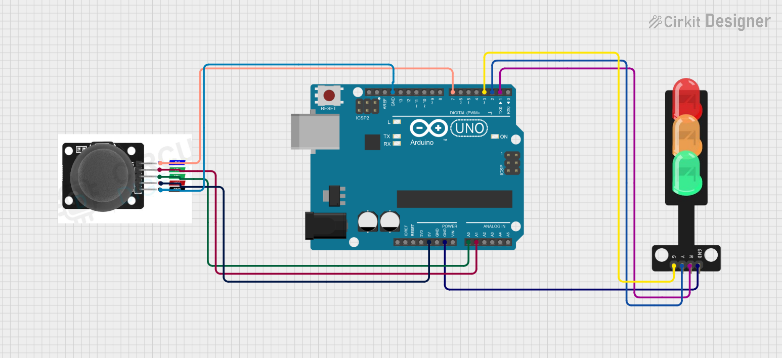
Example: Using with an Arduino UNO
The Junction 3 in 12 out can be used to distribute signals from an Arduino UNO to multiple devices. Below is an example code snippet to demonstrate this:
// Example: Distributing signals from Arduino UNO to multiple outputs
// This code sends HIGH and LOW signals to three input pins of the junction
// component, which then distributes the signals to the corresponding outputs.

const int inputPin1 = 2; // Arduino pin connected to IN1
const int inputPin2 = 3; // Arduino pin connected to IN2
const int inputPin3 = 4; // Arduino pin connected to IN3

void setup() {
  // Set the input pins as outputs
  pinMode(inputPin1, OUTPUT);
  pinMode(inputPin2, OUTPUT);
  pinMode(inputPin3, OUTPUT);
}

void loop() {
  // Send HIGH signal to IN1, LOW to IN2, and HIGH to IN3
  digitalWrite(inputPin1, HIGH);
  digitalWrite(inputPin2, LOW);
  digitalWrite(inputPin3, HIGH);

  delay(1000); // Wait for 1 second

  // Toggle the signals
  digitalWrite(inputPin1, LOW);
  digitalWrite(inputPin2, HIGH);
  digitalWrite(inputPin3, LOW);

  delay(1000); // Wait for 1 second
}
Troubleshooting and FAQs
Common Issues and Solutions
No Signal at Outputs
- Cause: Input signals are not connected or are below the required voltage.
- Solution: Verify the input connections and ensure the input signals meet the voltage and current requirements.
Signal Degradation
- Cause: Long or high-resistance connections.
- Solution: Use shorter and thicker wires to reduce resistance and signal loss.
Overheating
- Cause: Exceeding the maximum current rating.
- Solution: Ensure the total current drawn by all outputs does not exceed 2A per channel.
Interference Between Signals
- Cause: Lack of proper isolation between input signals.
- Solution: Use decoupling capacitors or signal isolators to minimize interference.
FAQs
Q: Can this component handle AC signals?
A: Yes, the Junction 3 in 12 out can handle both AC and DC signals, provided the voltage and current ratings are not exceeded.
Q: Can I use this component for power distribution?
A: Yes, it can be used for low-power distribution, but ensure the total current does not exceed 2A per channel.
Q: How do I test the component before use?
A: Use a multimeter to check continuity between the input and corresponding output pins. Ensure there are no short circuits.
Q: Can I connect fewer than 12 outputs?
A: Yes, you can connect as many or as few outputs as needed. Unused outputs will remain inactive.