How to Use PCA9685: Examples, Pinouts, and Specs
Introduction
The PCA9685 is a 16-channel, 12-bit Pulse Width Modulation (PWM) controller that communicates via the I2C protocol. It is widely used in robotics, automation, and lighting projects to control servos, LEDs, and other PWM-driven devices. This component simplifies the process of generating precise PWM signals, making it ideal for applications requiring multiple independent PWM outputs.
Explore Projects Built with PCA9685
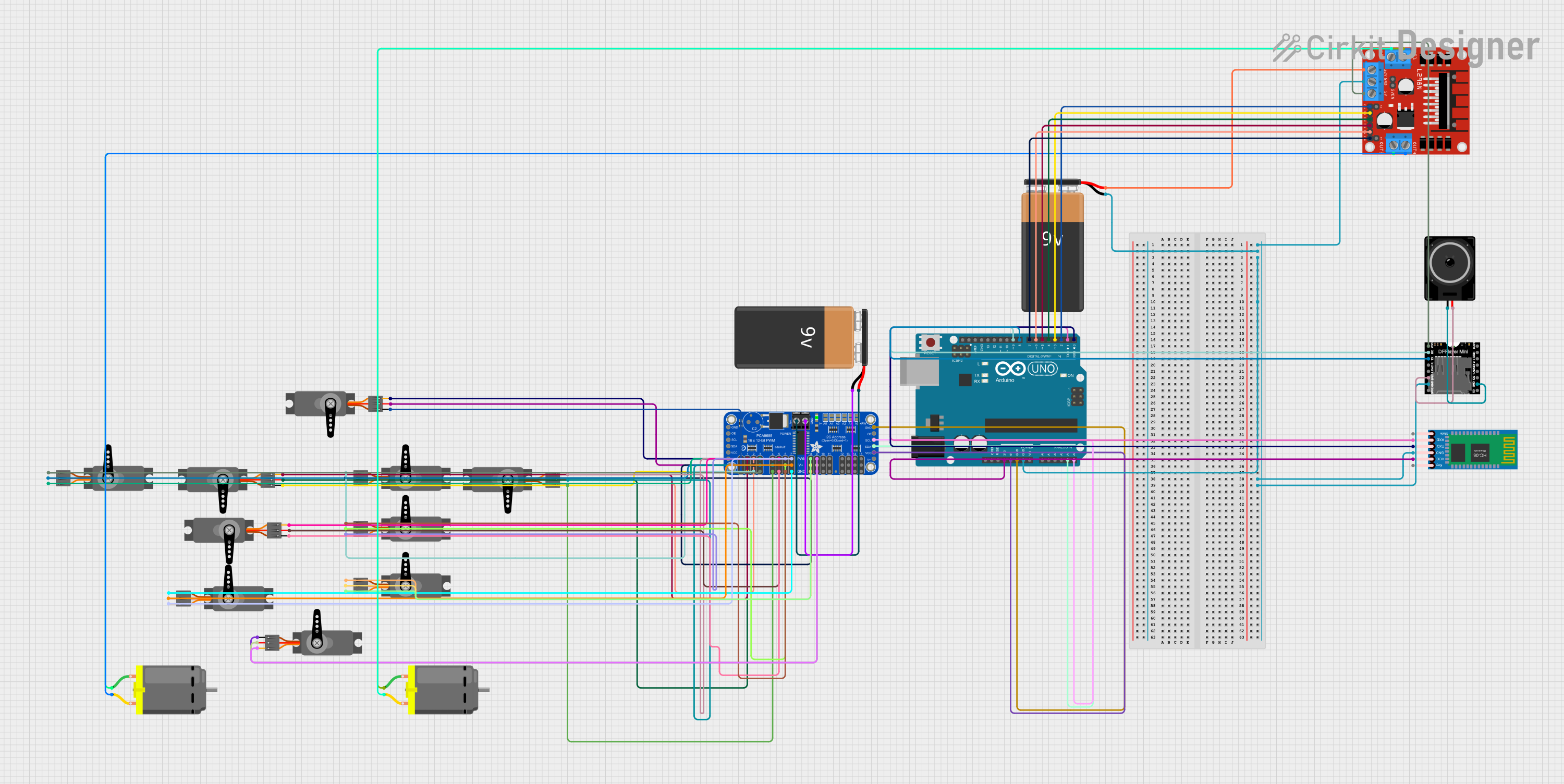
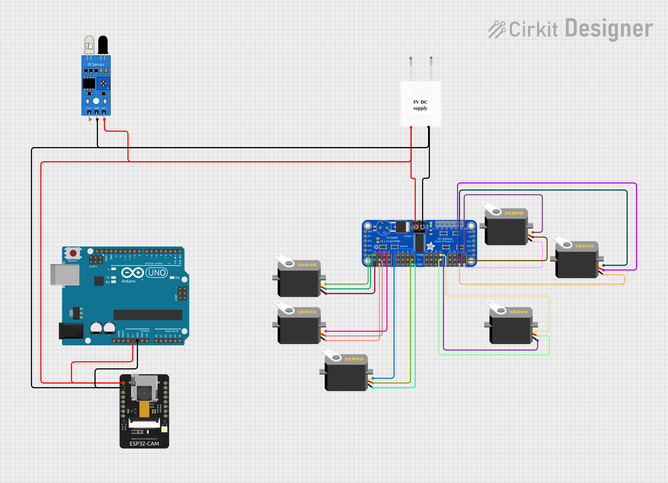

Explore Projects Built with PCA9685
Common Applications
- Controlling servo motors in robotic arms, drones, and RC vehicles
- Driving LED arrays for lighting and display systems
- Automation systems requiring multiple PWM outputs
- Motor speed control in small-scale projects
Technical Specifications
The PCA9685 is a versatile and powerful PWM controller. Below are its key technical details:
| Parameter | Value |
|---|---|
| Operating Voltage | 2.3V to 5.5V |
| PWM Resolution | 12-bit (4096 steps) |
| Number of Channels | 16 |
| Communication Protocol | I2C |
| I2C Address Range | 0x40 to 0x7F (configurable) |
| Maximum PWM Frequency | 1.6 kHz |
| Output Current per Pin | 25 mA (max) |
| Total Output Current | 400 mA (max) |
| Operating Temperature | -40°C to +85°C |
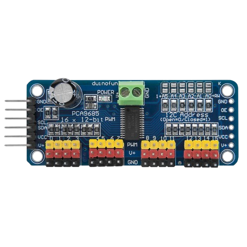
Pin Configuration
The PCA9685 is typically available in a 28-pin package. Below is the pinout description:
| Pin | Name | Description |
|---|---|---|
| 1-16 | PWM0-PWM15 | 16 PWM output channels for driving servos, LEDs, or other devices |
| 17 | VCC | Power supply input (2.3V to 5.5V) |
| 18 | GND | Ground connection |
| 19 | SDA | I2C data line |
| 20 | SCL | I2C clock line |
| 21 | OE | Output enable (active low, can disable all outputs when pulled high) |
| 22-27 | A0-A5 | I2C address selection pins (used to set the I2C address of the device) |
| 28 | V+ | External power supply for driving high-current devices (e.g., servos or LEDs) |
Usage Instructions
How to Use the PCA9685 in a Circuit
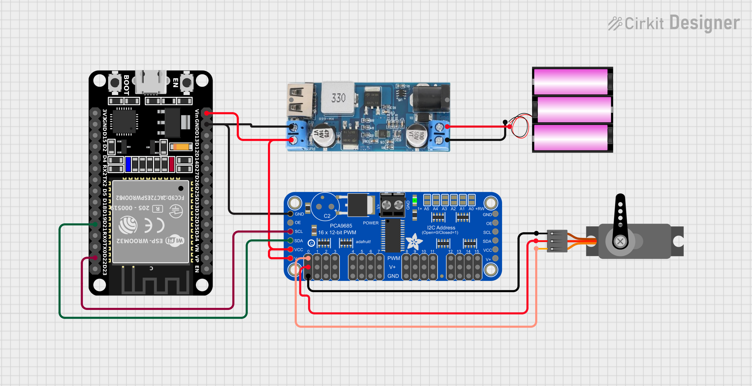
- Powering the PCA9685: Connect the VCC pin to a 3.3V or 5V power source and the GND pin to ground. If driving high-current devices like servos, connect an external power supply to the V+ pin.
- I2C Communication: Connect the SDA and SCL pins to the corresponding I2C pins on your microcontroller. Pull-up resistors (typically 4.7kΩ) may be required on the SDA and SCL lines.
- Address Configuration: Use the A0-A5 pins to set the I2C address of the PCA9685. This allows multiple PCA9685 modules to be used on the same I2C bus.
- Connecting Devices: Attach servos, LEDs, or other PWM-driven devices to the PWM0-PWM15 output pins.
Best Practices
- Use decoupling capacitors (e.g., 0.1µF) near the VCC and GND pins to reduce noise.
- Ensure the total current drawn by all connected devices does not exceed the PCA9685's maximum current rating.
- For servo motors, use an external power supply connected to the V+ pin to prevent overloading the PCA9685.
Example: Using PCA9685 with Arduino UNO
Below is an example of how to control a servo motor using the PCA9685 and an Arduino UNO:
#include <Wire.h>
#include <Adafruit_PWMServoDriver.h>

// Create an instance of the PCA9685 driver
Adafruit_PWMServoDriver pwm = Adafruit_PWMServoDriver();

void setup() {
  // Initialize serial communication for debugging
  Serial.begin(9600);
  Serial.println("Initializing PCA9685...");

  // Initialize the PCA9685 module
  pwm.begin();
  pwm.setPWMFreq(50); // Set PWM frequency to 50 Hz (common for servos)
}

void loop() {
  // Define the servo's min and max pulse lengths
  uint16_t servoMin = 150; // Minimum pulse length (0 degrees)
  uint16_t servoMax = 600; // Maximum pulse length (180 degrees)

  // Sweep the servo from 0 to 180 degrees
  for (uint16_t pulse = servoMin; pulse <= servoMax; pulse++) {
    pwm.setPWM(0, 0, pulse); // Channel 0, start at 0, set pulse width
    delay(10); // Small delay for smooth movement
  }

  // Sweep the servo back from 180 to 0 degrees
  for (uint16_t pulse = servoMax; pulse >= servoMin; pulse--) {
    pwm.setPWM(0, 0, pulse); // Channel 0, start at 0, set pulse width
    delay(10); // Small delay for smooth movement
  }
}
Notes
- The
Adafruit_PWMServoDriverlibrary is required for this example. Install it via the Arduino Library Manager. - Adjust the
servoMinandservoMaxvalues based on your specific servo motor's requirements.
Troubleshooting and FAQs
Common Issues
No Response from PCA9685
- Ensure the I2C connections (SDA, SCL) are correct and have proper pull-up resistors.
- Verify the I2C address matches the one configured on the PCA9685.
Servos or LEDs Not Working
- Check the external power supply connected to the V+ pin.
- Ensure the PWM frequency is set correctly for the connected devices (e.g., 50 Hz for servos).
Overheating
- Ensure the total current drawn by all devices does not exceed the PCA9685's maximum rating.
- Use an external power supply for high-current devices.
FAQs
Q: Can I use multiple PCA9685 modules on the same I2C bus?
A: Yes, you can connect up to 62 PCA9685 modules by configuring their I2C addresses using the A0-A5 pins.
Q: What is the maximum number of servos I can control with one PCA9685?
A: You can control up to 16 servos per PCA9685 module. For more servos, use additional modules.
Q: Can the PCA9685 drive high-power LEDs directly?
A: No, the PCA9685 outputs are limited to 25 mA per channel. Use external transistors or MOSFETs for high-power LEDs.
Q: What is the default I2C address of the PCA9685?
A: The default I2C address is 0x40.