
How to Use 4 x AA Battery Mount: Examples, Pinouts, and Specs
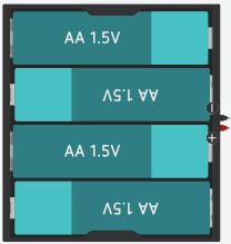
 Design with 4 x AA Battery Mount in Cirkit Designer
Introduction
The 4 x AA Battery Mount (Manufacturer: Adafruit, Part ID: 4AA Battery) is a compact and durable holder designed to securely house four AA batteries in series. This configuration provides a reliable power source for a wide range of electronic projects, delivering a nominal voltage of 6V (1.5V per battery). The holder is equipped with leads for easy integration into circuits, making it an essential component for powering small to medium-sized devices.
Explore Projects Built with 4 x AA Battery Mount
 Open Project in Cirkit Designer
 Open Project in Cirkit Designer
 Open Project in Cirkit Designer
 Open Project in Cirkit Designer
Explore Projects Built with 4 x AA Battery Mount
Open Project in Cirkit DesignerOpen Project in Cirkit DesignerOpen Project in Cirkit DesignerOpen Project in Cirkit DesignerCommon Applications and Use Cases
- Powering microcontroller-based projects (e.g., Arduino, Raspberry Pi peripherals)
- Portable electronic devices
- Robotics and motorized systems
- Prototyping and testing circuits
- Educational and DIY electronics projects
Technical Specifications
The following table outlines the key technical details of the 4 x AA Battery Mount:
| Specification | Details |
|---|---|
| Manufacturer | Adafruit |
| Part ID | 4AA Battery |
| Battery Configuration | 4 x AA batteries in series |
| Nominal Output Voltage | 6V (1.5V per battery x 4) |
| Maximum Output Current | Dependent on the battery type (e.g., alkaline, NiMH, or lithium) |
| Lead Type | Pre-attached red (positive) and black (negative) wires |
| Wire Length | Approximately 6 inches (15 cm) |
| Dimensions | 58mm x 62mm x 15mm (L x W x H) |
| Material | Durable plastic with metal battery contacts |
| Mounting Options | Screw holes for secure mounting or adhesive tape compatibility |
Pin Configuration and Descriptions
The 4 x AA Battery Mount does not have traditional pins but includes two pre-attached wires for electrical connections. The table below describes the wires:
| Wire Color | Function | Description |
|---|---|---|
| Red | Positive (+) Terminal | Connects to the positive terminal of the circuit or power input. |
| Black | Negative (-) Terminal | Connects to the ground (GND) or negative terminal of the circuit. |
Usage Instructions
How to Use the Component in a Circuit
- Insert Batteries: Place four AA batteries into the holder, ensuring correct polarity as indicated on the holder.
- Connect Wires:
- Attach the red wire to the positive terminal of your circuit or device.
- Attach the black wire to the ground (GND) or negative terminal of your circuit.
- Secure the Holder:
- Use screws or adhesive tape to mount the holder securely in your project enclosure, if necessary.
- Test the Voltage:
- Use a multimeter to verify the output voltage (approximately 6V with fresh batteries) before connecting to your circuit.
Important Considerations and Best Practices
- Battery Type: Use batteries of the same type and charge level (e.g., all alkaline or all NiMH) to ensure consistent performance.
- Current Requirements: Ensure the batteries can supply sufficient current for your circuit. High-drain devices may require high-capacity batteries.
- Polarity: Double-check the polarity of the connections to avoid damaging your circuit.
- Battery Life: Monitor battery life and replace or recharge batteries as needed to maintain consistent power output.
- Short Circuit Protection: Avoid shorting the wires to prevent overheating or damage to the batteries.
Example: Connecting to an Arduino UNO
The 4 x AA Battery Mount can be used to power an Arduino UNO via its VIN and GND pins. Below is an example circuit and code:
Circuit Connection
- Connect the red wire from the battery holder to the VIN pin on the Arduino UNO.
- Connect the black wire from the battery holder to the GND pin on the Arduino UNO.
Example Code
// Example code to blink an LED using an Arduino UNO powered by a 4 x AA Battery Mount

const int ledPin = 13; // Pin connected to the built-in LED on the Arduino

void setup() {
  pinMode(ledPin, OUTPUT); // Set the LED pin as an output
}

void loop() {
  digitalWrite(ledPin, HIGH); // Turn the LED on
  delay(1000);               // Wait for 1 second
  digitalWrite(ledPin, LOW);  // Turn the LED off
  delay(1000);               // Wait for 1 second
}
Note: Ensure the total voltage from the battery holder does not exceed the Arduino's input voltage limits (6-12V for VIN).
Troubleshooting and FAQs
Common Issues Users Might Face
No Power Output:
- Cause: Batteries are inserted incorrectly or are depleted.
- Solution: Check the battery orientation and replace with fresh batteries if necessary.
Overheating Wires:
- Cause: Short circuit or excessive current draw.
- Solution: Inspect the circuit for shorts and ensure the connected device does not exceed the battery's current capacity.
Inconsistent Voltage:
- Cause: Mixed battery types or uneven charge levels.
- Solution: Use batteries of the same type and charge level.
Loose Connections:
- Cause: Poor contact between the wires and the circuit.
- Solution: Securely solder or use proper connectors for reliable connections.
FAQs
Q: Can I use rechargeable batteries with this holder?
A: Yes, the holder is compatible with rechargeable AA batteries such as NiMH or lithium-ion. Ensure the total voltage matches your circuit's requirements.
Q: What is the maximum current this holder can handle?
A: The maximum current depends on the type of batteries used. Check the battery specifications for current ratings.
Q: Can I use fewer than four batteries in this holder?
A: No, the holder is designed for four batteries in series. Using fewer batteries will result in an incomplete circuit.
Q: Is the holder waterproof?
A: No, the holder is not waterproof. Avoid exposing it to moisture or water to prevent damage.