How to Use Solar Alignment & Monitoring Shield: Examples, Pinouts, and Specs
Introduction
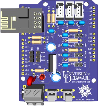
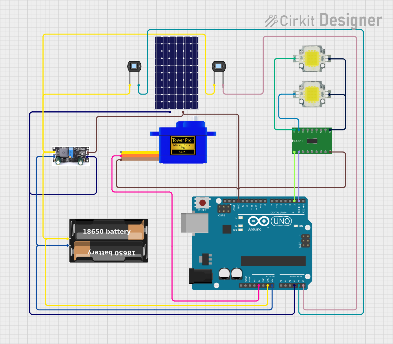
The Solar Alignment & Monitoring Shield is a specialized device designed to optimize the positioning of solar panels by monitoring their alignment with the sun. By ensuring that solar panels are always oriented to capture the maximum amount of sunlight, this shield significantly enhances energy efficiency and output. It integrates seamlessly with microcontrollers like the Arduino UNO, making it ideal for both DIY solar projects and professional solar tracking systems.
Explore Projects Built with Solar Alignment & Monitoring Shield
Explore Projects Built with Solar Alignment & Monitoring Shield
Common Applications and Use Cases
- Solar panel tracking systems for residential and commercial installations.
- Educational projects to demonstrate solar energy optimization.
- Research and development in renewable energy technologies.
- Integration into IoT-based energy monitoring systems.
Technical Specifications
The Solar Alignment & Monitoring Shield is equipped with sensors and circuitry to detect sunlight intensity and direction. Below are its key technical details:
General Specifications
| Parameter | Value |
|---|---|
| Operating Voltage | 5V DC (via Arduino or external power supply) |
| Current Consumption | 50 mA (typical) |
| Light Sensor Type | Photodiodes or LDRs (4 sensors) |
| Communication Interface | Analog and Digital Pins |
| Operating Temperature | -20°C to 60°C |
| Dimensions | 70mm x 55mm x 20mm |
Pin Configuration and Descriptions
| Pin Name | Type | Description |
|---|---|---|
| A0 | Analog In | Reads light intensity from Sensor 1 (North) |
| A1 | Analog In | Reads light intensity from Sensor 2 (East) |
| A2 | Analog In | Reads light intensity from Sensor 3 (South) |
| A3 | Analog In | Reads light intensity from Sensor 4 (West) |
| D2 | Digital Out | Controls horizontal motor (PWM signal) |
| D3 | Digital Out | Controls vertical motor (PWM signal) |
| GND | Ground | Connects to the ground of the power supply |
| 5V | Power | Supplies 5V power to the shield |
Usage Instructions
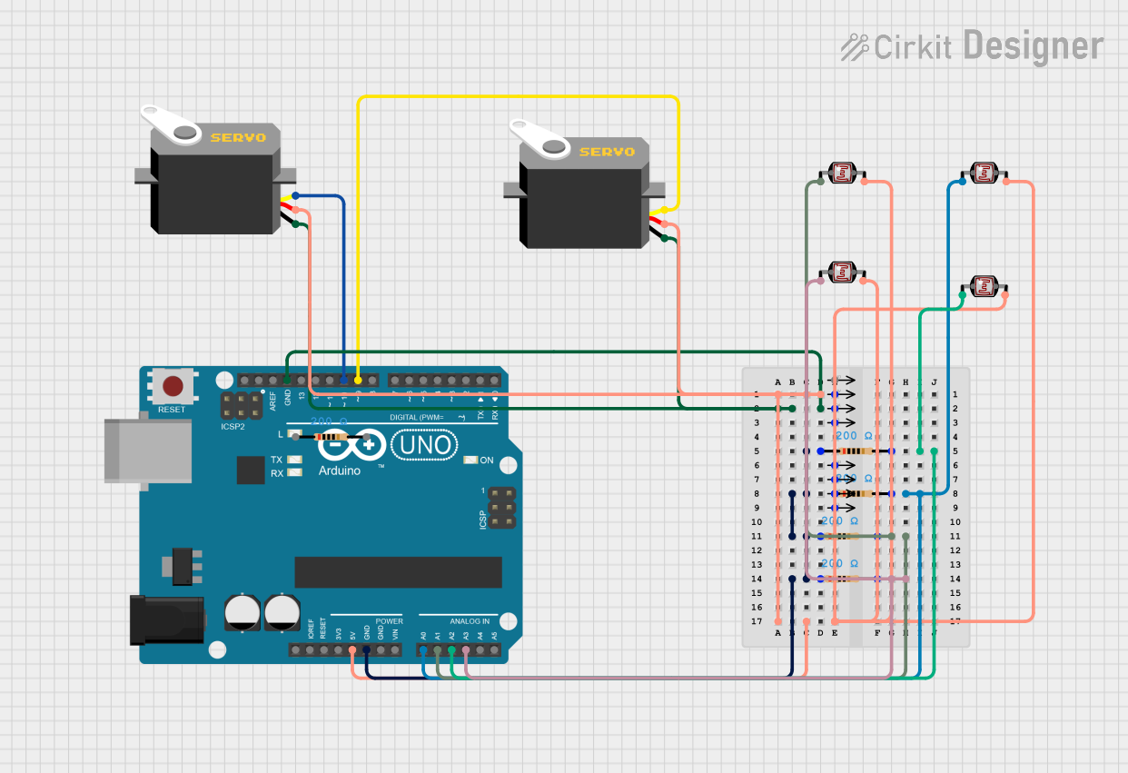
How to Use the Component in a Circuit
- Mount the Shield: Place the Solar Alignment & Monitoring Shield on top of an Arduino UNO or compatible microcontroller.
- Connect the Motors: Attach the horizontal and vertical motors to the shield's motor control outputs (D2 and D3).
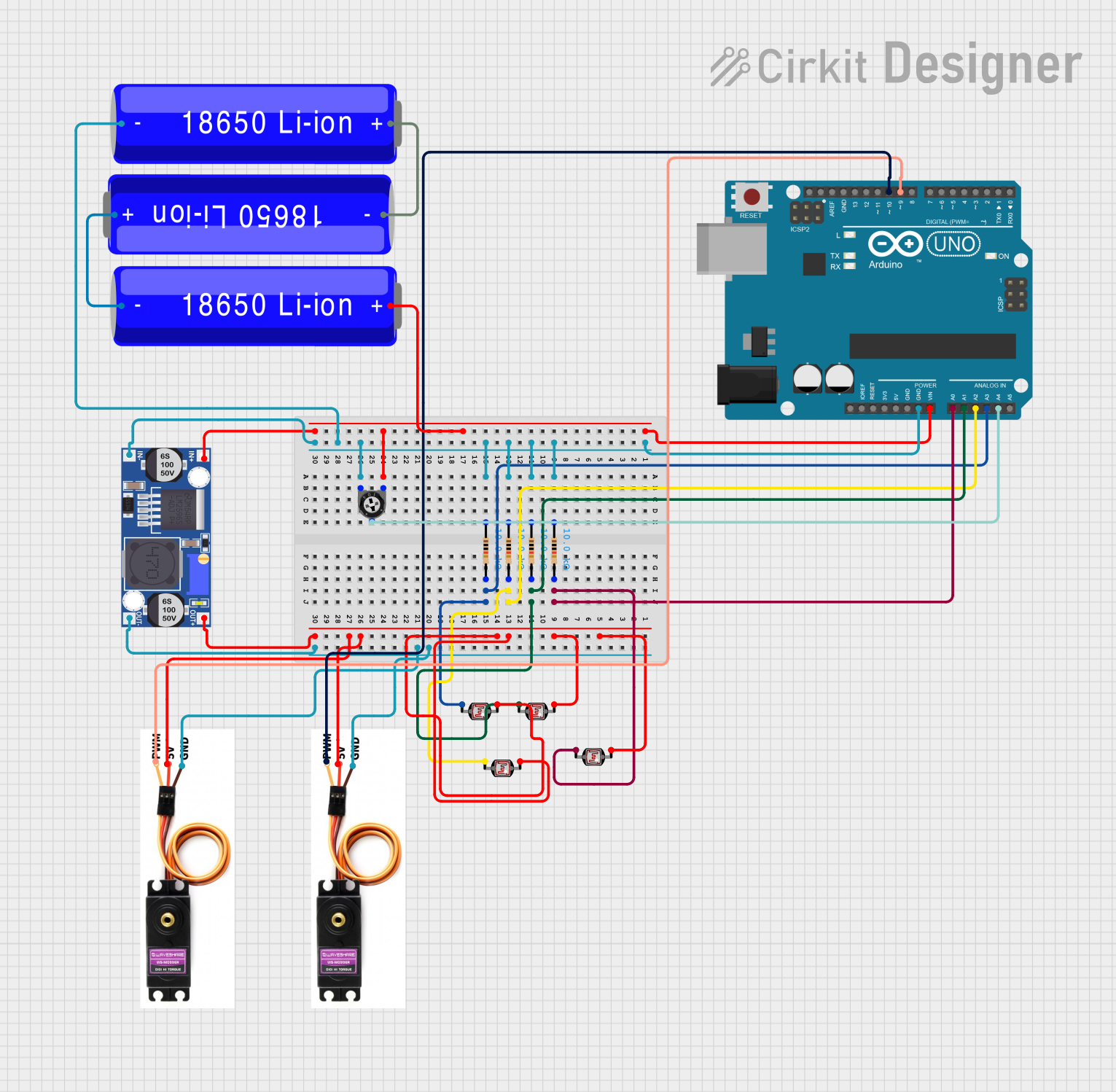
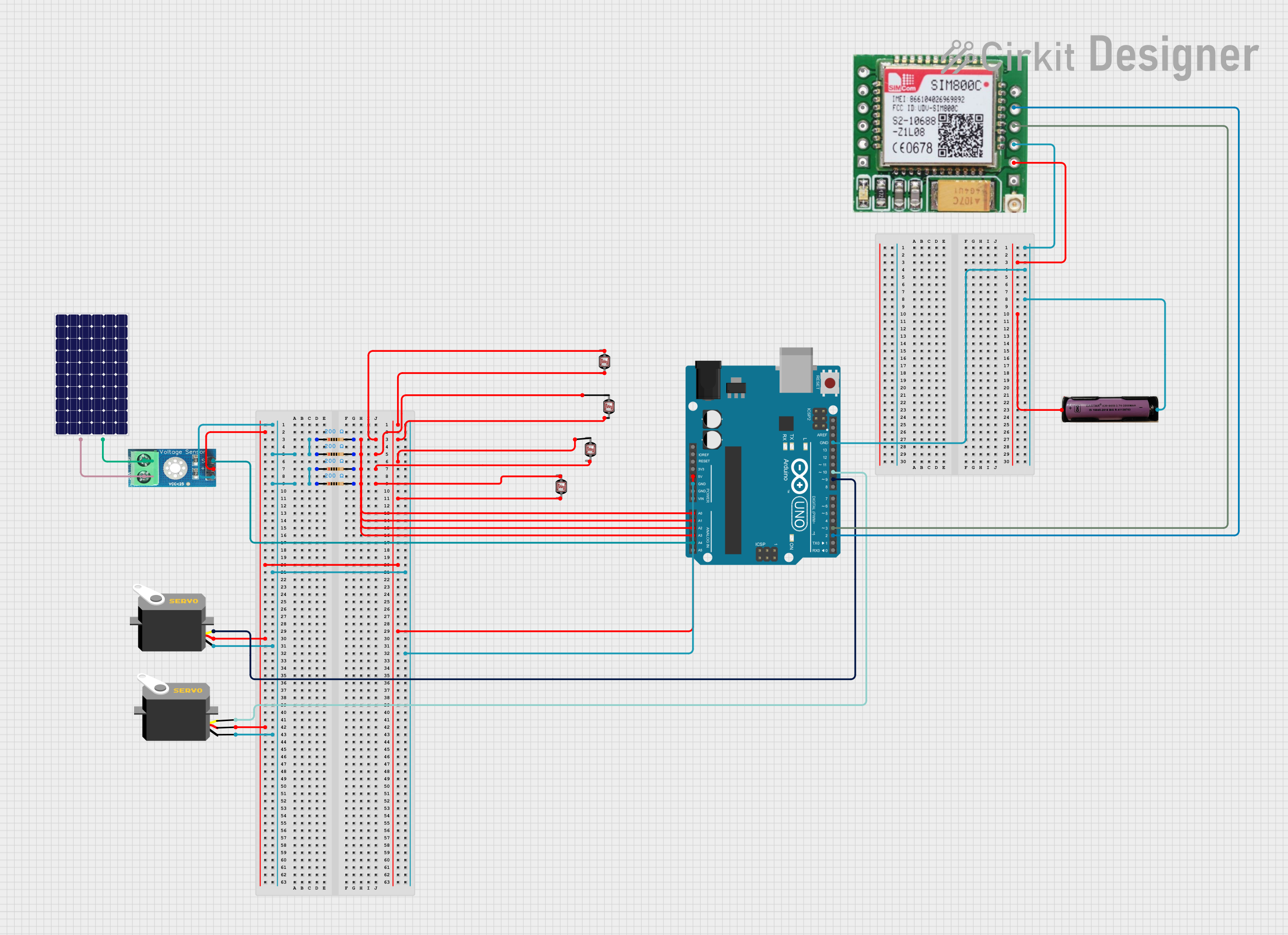
- Power the System: Supply 5V DC power to the Arduino, which will also power the shield.
- Read Sensor Data: Use the analog pins (A0 to A3) to read light intensity values from the four sensors.
- Control Motors: Use the sensor data to adjust the motors and align the solar panel for maximum sunlight exposure.
Important Considerations and Best Practices
- Calibration: Ensure the sensors are calibrated for accurate sunlight detection. This can be done by testing the shield in a controlled environment.
- Motor Compatibility: Use motors that are compatible with the shield's output voltage and current ratings.
- Environmental Protection: Protect the shield and sensors from harsh weather conditions by using a waterproof enclosure.
- Code Optimization: Implement efficient algorithms to avoid unnecessary motor movements, which can save energy.
Example Code for Arduino UNO
Below is an example code snippet to read sensor data and control motors for solar alignment:
// Define sensor pins
const int sensorNorth = A0;
const int sensorEast = A1;
const int sensorSouth = A2;
const int sensorWest = A3;

// Define motor control pins
const int motorHorizontal = 2;
const int motorVertical = 3;

void setup() {
  // Initialize serial communication for debugging
  Serial.begin(9600);

  // Set motor pins as outputs
  pinMode(motorHorizontal, OUTPUT);
  pinMode(motorVertical, OUTPUT);
}

void loop() {
  // Read light intensity from sensors
  int northValue = analogRead(sensorNorth);
  int eastValue = analogRead(sensorEast);
  int southValue = analogRead(sensorSouth);
  int westValue = analogRead(sensorWest);

  // Print sensor values for debugging
  Serial.print("North: "); Serial.print(northValue);
  Serial.print(" East: "); Serial.print(eastValue);
  Serial.print(" South: "); Serial.print(southValue);
  Serial.print(" West: "); Serial.println(westValue);

  // Calculate motor control signals (basic example)
  int horizontalControl = eastValue - westValue;
  int verticalControl = northValue - southValue;

  // Map control signals to PWM range (0-255)
  horizontalControl = map(horizontalControl, -1023, 1023, 0, 255);
  verticalControl = map(verticalControl, -1023, 1023, 0, 255);

  // Write control signals to motors
  analogWrite(motorHorizontal, constrain(horizontalControl, 0, 255));
  analogWrite(motorVertical, constrain(verticalControl, 0, 255));

  // Delay for stability
  delay(100);
}
Troubleshooting and FAQs
Common Issues and Solutions
No Sensor Readings:
- Cause: Loose connections or faulty sensors.
- Solution: Check all connections and ensure the sensors are functioning properly.
Motors Not Moving:
- Cause: Incorrect motor wiring or insufficient power supply.
- Solution: Verify motor connections and ensure the power supply meets the motor's requirements.
Inaccurate Alignment:
- Cause: Miscalibrated sensors or incorrect control algorithm.
- Solution: Recalibrate the sensors and refine the control algorithm.
Overheating:
- Cause: Prolonged motor operation or high ambient temperature.
- Solution: Use heat sinks or cooling mechanisms for the motors and shield.
FAQs
Q1: Can this shield be used with other microcontrollers besides Arduino UNO?
A1: Yes, the shield is compatible with other Arduino boards and microcontrollers that support 5V logic and have analog input pins.
Q2: How do I protect the shield from rain and dust?
A2: Use a weatherproof enclosure to house the shield and sensors while ensuring the sensors remain exposed to sunlight.
Q3: Can I use this shield for a dual-axis solar tracker?
A3: Yes, the shield supports dual-axis tracking by controlling both horizontal and vertical motors.
Q4: What type of motors should I use?
A4: Use DC motors or servo motors that are compatible with the shield's output voltage and current ratings.