How to Use SIMCOM A7670SA: Examples, Pinouts, and Specs
Introduction
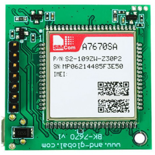
The SIMCOM A7670SA is a compact GSM/GPRS module designed for Internet of Things (IoT) applications. Manufactured by Simcom, this module provides reliable cellular connectivity with support for multiple communication protocols, including GSM, GPRS, and SMS. It also features built-in GPS functionality, enabling precise location tracking. With its low power consumption, the A7670SA is ideal for battery-operated devices and applications requiring efficient and continuous connectivity.
Explore Projects Built with SIMCOM A7670SA


Explore Projects Built with SIMCOM A7670SA
Common Applications and Use Cases
- IoT devices and smart systems
- Asset tracking and fleet management
- Remote monitoring and control
- Wearable devices with GPS functionality
- Smart metering and telemetry
- Security and surveillance systems
Technical Specifications
Key Technical Details
| Parameter | Specification |
|---|---|
| Manufacturer | Simcom |
| Part ID | A7670SA |
| Cellular Connectivity | GSM/GPRS (2G) |
| Frequency Bands | GSM 850/900/1800/1900 MHz |
| GPS Support | Yes (Integrated GPS functionality) |
| Data Transmission | GPRS Class 12, SMS (Text and PDU mode) |
| Power Supply Voltage | 3.4V to 4.2V |
| Operating Temperature | -40°C to +85°C |
| Dimensions | 19.8mm x 19.8mm x 2.15mm |
| Power Consumption (Idle) | < 1mA |
| Power Consumption (Active) | ~350mA (during transmission) |
| Interface | UART, GPIO, ADC, SIM card interface |
Pin Configuration and Descriptions
The SIMCOM A7670SA module has multiple pins for communication and power. Below is the pin configuration:
| Pin Number | Pin Name | Description |
|---|---|---|
| 1 | VCC | Power supply input (3.4V to 4.2V) |
| 2 | GND | Ground |
| 3 | TXD | UART Transmit Data |
| 4 | RXD | UART Receive Data |
| 5 | SIM_VDD | SIM card power supply |
| 6 | SIM_CLK | SIM card clock signal |
| 7 | SIM_DATA | SIM card data signal |
| 8 | SIM_RST | SIM card reset signal |
| 9 | GPS_TXD | GPS UART Transmit Data |
| 10 | GPS_RXD | GPS UART Receive Data |
| 11 | GPIO1 | General Purpose Input/Output 1 |
| 12 | GPIO2 | General Purpose Input/Output 2 |
| 13 | ADC | Analog-to-Digital Converter input |
| 14 | RESET | Module reset (active low) |
Usage Instructions
How to Use the SIMCOM A7670SA in a Circuit
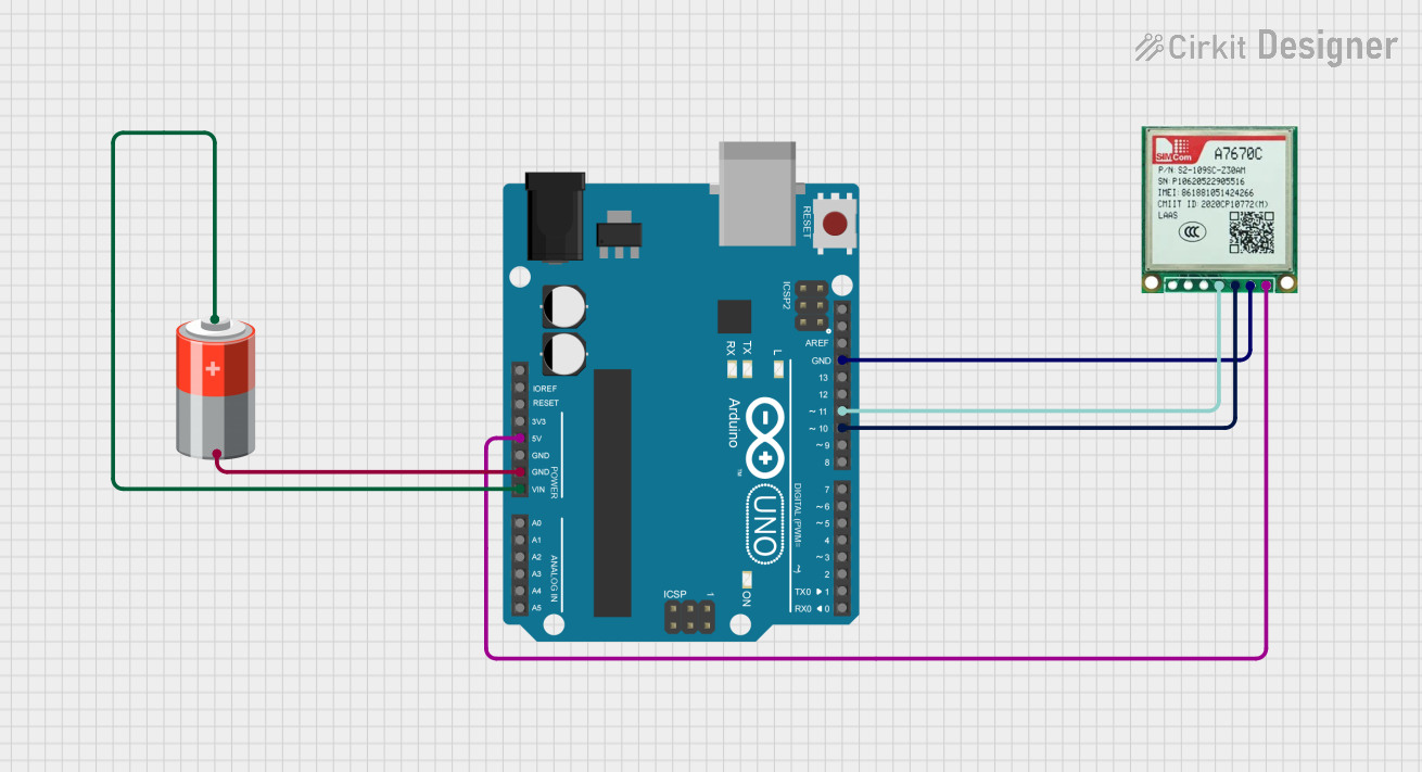
- Power Supply: Connect the VCC pin to a regulated power source (3.4V to 4.2V) and the GND pin to ground. Ensure the power supply can handle peak currents of up to 2A during transmission.
- UART Communication: Connect the TXD and RXD pins to the UART interface of your microcontroller or development board (e.g., Arduino UNO). Use a logic level converter if your microcontroller operates at 5V logic levels.
- SIM Card Interface: Insert a valid SIM card into the SIM card holder and connect the SIM_VDD, SIM_CLK, SIM_DATA, and SIM_RST pins to the corresponding signals.
- GPS Functionality: Use the GPS_TXD and GPS_RXD pins to communicate with the GPS module. Ensure the GPS antenna is properly connected for accurate location tracking.
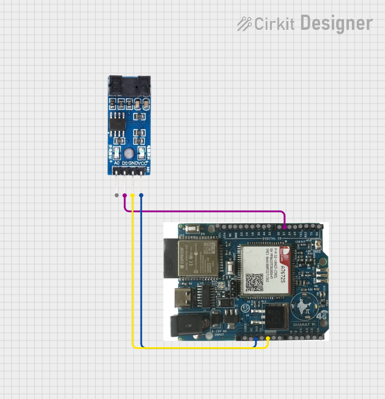
- GPIO and ADC: Use the GPIO pins for custom input/output operations and the ADC pin for analog signal measurements.
- Reset: Connect the RESET pin to a push-button or microcontroller pin for resetting the module when needed.
Important Considerations and Best Practices
- Use decoupling capacitors near the VCC pin to stabilize the power supply and reduce noise.
- Ensure proper grounding to avoid communication errors and interference.
- Use an external antenna for both GSM and GPS to maximize signal strength.
- Avoid exposing the module to voltages outside its specified range to prevent damage.
- For Arduino UNO users, use a software serial library to communicate with the module, as the hardware UART is typically used for programming.
Example Code for Arduino UNO
Below is an example of how to send an SMS using the SIMCOM A7670SA module with an Arduino UNO:
#include <SoftwareSerial.h>

// Define RX and TX pins for SoftwareSerial
SoftwareSerial simModule(10, 11); // RX = Pin 10, TX = Pin 11

void setup() {
  // Initialize serial communication
  Serial.begin(9600); // For debugging
  simModule.begin(9600); // For SIMCOM A7670SA communication

  // Wait for the module to initialize
  delay(1000);
  Serial.println("Initializing SIMCOM A7670SA...");

  // Send AT command to check communication
  simModule.println("AT");
  delay(1000);
  while (simModule.available()) {
    Serial.write(simModule.read());
  }

  // Set SMS text mode
  simModule.println("AT+CMGF=1"); // Set SMS to text mode
  delay(1000);

  // Send SMS
  simModule.println("AT+CMGS=\"+1234567890\""); // Replace with recipient's number
  delay(1000);
  simModule.println("Hello from SIMCOM A7670SA!"); // SMS content
  delay(1000);
  simModule.write(26); // Send Ctrl+Z to indicate end of message
  delay(5000);

  Serial.println("SMS sent!");
}

void loop() {
  // Nothing to do here
}
Troubleshooting and FAQs
Common Issues and Solutions
Module Not Responding to AT Commands
- Ensure the power supply voltage is within the specified range (3.4V to 4.2V).
- Check the UART connections (TXD and RXD) and ensure they are not swapped.
- Verify that the baud rate matches the module's default (9600 bps).
No GPS Signal
- Ensure the GPS antenna is properly connected and positioned in an open area.
- Allow sufficient time for the GPS module to acquire satellite signals.
SIM Card Not Detected
- Verify that the SIM card is inserted correctly and is active.
- Check the connections to the SIM card interface pins (SIM_VDD, SIM_CLK, SIM_DATA, SIM_RST).
High Power Consumption
- Use a power supply capable of handling peak currents of up to 2A.
- Enable power-saving modes using AT commands if applicable.
FAQs
Q: Can the A7670SA module work with 5V logic levels?
A: No, the module operates at 3.3V logic levels. Use a logic level converter if your microcontroller operates at 5V.
Q: How do I reset the module?
A: Pull the RESET pin low for at least 100ms and then release it to reset the module.
Q: Does the module support 3G or 4G networks?
A: No, the A7670SA only supports GSM/GPRS (2G) networks.
Q: Can I use the module for voice calls?
A: Yes, the module supports voice call functionality using AT commands.
Q: How do I update the firmware?
A: Firmware updates can be performed via the UART interface using Simcom's official tools and documentation.