Cirkit Designer Logo
Cirkit Designer
Your all-in-one circuit design IDE
Home / 
Component Documentation

How to Use MKR Connector Carrier: Examples, Pinouts, and Specs

Image of MKR Connector Carrier
Cirkit Designer LogoDesign with MKR Connector Carrier in Cirkit Designer

Introduction

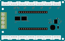
The MKR Connector Carrier (Manufacturer Part ID: 28-18) is a versatile carrier board designed by Arduino to expand the connectivity and functionality of MKR series microcontrollers. It simplifies the integration of sensors, actuators, and other modules by providing a variety of Grove connectors and additional interfaces. This carrier board is ideal for rapid prototyping, IoT applications, and educational projects, enabling users to quickly connect and test components without the need for complex wiring.

Explore Projects Built with MKR Connector Carrier

Use Cirkit Designer to design, explore, and prototype these projects online. Some projects support real-time simulation. Click "Open Project" to start designing instantly!
Arduino MKR WiFi 1010 Basic Power Supply with Voltage Divider
Image of voltqge divider: A project utilizing MKR Connector Carrier in a practical application
This circuit features an Arduino MKR WiFi 1010 powered by a 4xAA battery holder, with the battery's positive terminal connected to the Arduino's VIN pin and the negative terminal to GND. Two 100k Ohm resistors are connected in series between the Arduino's A0 analog input and VCC, with their midpoint also tied to GND, forming a voltage divider that could be used for sensing or reference voltage purposes.
Cirkit Designer LogoOpen Project in Cirkit Designer
Arduino MKR WiFi 1010 and Adafruit RFM9x LoRa Radio Communication System
Image of 1010: A project utilizing MKR Connector Carrier in a practical application
This circuit connects an Adafruit RFM9x LoRa Radio module to an Arduino MKR WiFi 1010 for wireless communication capabilities. The LoRa module's SPI interface (MOSI, MISO, SCK, CS) is connected to the corresponding SPI pins on the Arduino, allowing for serial data transfer between the devices. Additionally, the LoRa module's reset (RST) and interrupt (DIO0) pins are connected to digital pins on the Arduino for control and asynchronous communication.
Cirkit Designer LogoOpen Project in Cirkit Designer
MakerEdu Creator with Bluetooth, IR Sensors, LCD Display, and Push Button Interaction
Image of MKL Distance Measurement: A project utilizing MKR Connector Carrier in a practical application
This circuit features a MakerEdu Creator microcontroller board interfaced with two MKE-S11 IR Infrared Obstacle Avoidance Sensors, a MKE-M02 Push Button Tact Switch, a MKE-M15 Bluetooth module, and a MKE-M08 LCD2004 I2C display module. The push button is connected to a digital input for user interaction, while the IR sensors are likely used for detecting obstacles. The Bluetooth module enables wireless communication, and the LCD display provides a user interface for displaying information or statuses.
Cirkit Designer LogoOpen Project in Cirkit Designer
Arduino MKR WiFi 1010 Controlled Relay Switching Circuit
Image of Receptor lorawan: A project utilizing MKR Connector Carrier in a practical application
This circuit consists of an Arduino MKR WiFi 1010 microcontroller connected to a 5V relay. The Arduino is programmed to receive LoRa wireless communication signals and toggle the relay based on the received data, which controls the connection between the relay's Common terminal and either the Normally Open or Normally Closed terminal. The relay's activation is dependent on the specific message received ('button pressed'), which is intended to switch a connected external load on or off.
Cirkit Designer LogoOpen Project in Cirkit Designer

Explore Projects Built with MKR Connector Carrier

Use Cirkit Designer to design, explore, and prototype these projects online. Some projects support real-time simulation. Click "Open Project" to start designing instantly!
Image of voltqge divider: A project utilizing MKR Connector Carrier in a practical application
Arduino MKR WiFi 1010 Basic Power Supply with Voltage Divider
This circuit features an Arduino MKR WiFi 1010 powered by a 4xAA battery holder, with the battery's positive terminal connected to the Arduino's VIN pin and the negative terminal to GND. Two 100k Ohm resistors are connected in series between the Arduino's A0 analog input and VCC, with their midpoint also tied to GND, forming a voltage divider that could be used for sensing or reference voltage purposes.
Cirkit Designer LogoOpen Project in Cirkit Designer
Image of 1010: A project utilizing MKR Connector Carrier in a practical application
Arduino MKR WiFi 1010 and Adafruit RFM9x LoRa Radio Communication System
This circuit connects an Adafruit RFM9x LoRa Radio module to an Arduino MKR WiFi 1010 for wireless communication capabilities. The LoRa module's SPI interface (MOSI, MISO, SCK, CS) is connected to the corresponding SPI pins on the Arduino, allowing for serial data transfer between the devices. Additionally, the LoRa module's reset (RST) and interrupt (DIO0) pins are connected to digital pins on the Arduino for control and asynchronous communication.
Cirkit Designer LogoOpen Project in Cirkit Designer
Image of MKL Distance Measurement: A project utilizing MKR Connector Carrier in a practical application
MakerEdu Creator with Bluetooth, IR Sensors, LCD Display, and Push Button Interaction
This circuit features a MakerEdu Creator microcontroller board interfaced with two MKE-S11 IR Infrared Obstacle Avoidance Sensors, a MKE-M02 Push Button Tact Switch, a MKE-M15 Bluetooth module, and a MKE-M08 LCD2004 I2C display module. The push button is connected to a digital input for user interaction, while the IR sensors are likely used for detecting obstacles. The Bluetooth module enables wireless communication, and the LCD display provides a user interface for displaying information or statuses.
Cirkit Designer LogoOpen Project in Cirkit Designer
Image of Receptor lorawan: A project utilizing MKR Connector Carrier in a practical application
Arduino MKR WiFi 1010 Controlled Relay Switching Circuit
This circuit consists of an Arduino MKR WiFi 1010 microcontroller connected to a 5V relay. The Arduino is programmed to receive LoRa wireless communication signals and toggle the relay based on the received data, which controls the connection between the relay's Common terminal and either the Normally Open or Normally Closed terminal. The relay's activation is dependent on the specific message received ('button pressed'), which is intended to switch a connected external load on or off.
Cirkit Designer LogoOpen Project in Cirkit Designer

Common Applications and Use Cases

  • IoT projects requiring multiple sensor connections
  • Rapid prototyping with MKR series boards
  • Educational projects for learning about sensors and actuators
  • Smart home automation systems
  • Environmental monitoring and data logging

Technical Specifications

The MKR Connector Carrier is designed to work seamlessly with MKR series microcontrollers, offering a range of connectivity options. Below are the key technical details:

General Specifications

Parameter Value
Manufacturer Arduino
Part ID 28-18
Compatible Boards MKR series microcontrollers
Operating Voltage 3.3V
Dimensions 85mm x 55mm
Weight 25g

Pin Configuration and Descriptions

The MKR Connector Carrier features multiple Grove connectors and pin headers for easy interfacing. Below is a detailed description of the available connectors:

Grove Connectors

Connector Type Description Pinout (Signal)
Analog For analog sensors VCC, GND, Signal
Digital For digital sensors or actuators VCC, GND, Signal
I2C For I2C-compatible devices VCC, GND, SDA, SCL
UART For serial communication modules VCC, GND, TX, RX

Additional Interfaces

Interface Description Pinout
Power Input External power supply (optional) VIN, GND
MKR Header Connects to MKR microcontroller Matches MKR pinout

Usage Instructions

The MKR Connector Carrier is designed for plug-and-play operation with MKR series boards. Follow the steps below to use the carrier board effectively:

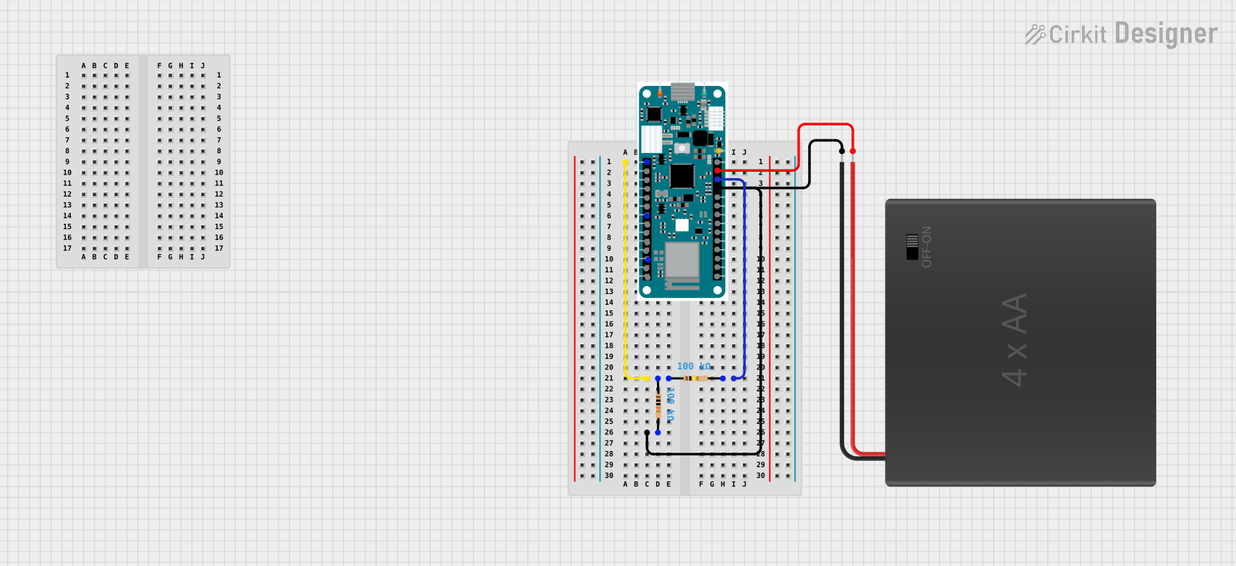
Step 1: Connect the MKR Board

  1. Align the MKR microcontroller with the MKR header on the carrier board.
  2. Gently press the MKR board into place, ensuring all pins are securely connected.

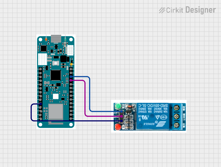
Step 2: Attach Sensors or Modules

  1. Identify the type of sensor or module you want to connect (e.g., analog, digital, I2C, UART).
  2. Use the appropriate Grove connector on the carrier board to connect the sensor/module.
  3. Ensure the connector is firmly seated to avoid loose connections.

Step 3: Power the System

  1. Power the MKR board via USB or an external power supply connected to the VIN and GND pins.
  2. Verify that the power LED on the MKR board and carrier board is lit.

Step 4: Write and Upload Code

  1. Open the Arduino IDE and select the appropriate MKR board from the "Tools" menu.
  2. Write or load a sketch that interacts with the connected sensors or modules.
  3. Upload the code to the MKR board via USB.

Example Code: Reading an Analog Sensor

The following example demonstrates how to read data from an analog sensor connected to the Grove Analog connector:

// Example: Reading an analog sensor connected to the MKR Connector Carrier
const int analogPin = A0; // Analog pin connected to the sensor

void setup() {
  Serial.begin(9600); // Initialize serial communication at 9600 baud
  while (!Serial);    // Wait for the serial monitor to open
  Serial.println("Analog Sensor Reading Example");
}

void loop() {
  int sensorValue = analogRead(analogPin); // Read the analog value
  Serial.print("Sensor Value: ");
  Serial.println(sensorValue); // Print the value to the serial monitor
  delay(500); // Wait for 500ms before the next reading
}

Best Practices

  • Always check the voltage and current requirements of connected sensors or modules to ensure compatibility.
  • Use short and secure connections to minimize signal interference.
  • Avoid connecting multiple high-power devices to prevent overloading the MKR board.

Troubleshooting and FAQs

Common Issues and Solutions

  1. No Power to the Carrier Board

    • Ensure the MKR board is properly seated in the MKR header.
    • Verify the power source (USB or external) is functioning correctly.
  2. Sensor/Module Not Responding

    • Double-check the connection type (analog, digital, I2C, UART) and use the correct Grove connector.
    • Verify the sensor/module is compatible with 3.3V logic levels.
  3. Incorrect Sensor Readings

    • Ensure the sensor is properly connected and powered.
    • Check for loose connections or damaged cables.
  4. Code Upload Fails

    • Confirm the correct MKR board is selected in the Arduino IDE.
    • Ensure the USB cable is properly connected and functional.

FAQs

Q: Can I use the MKR Connector Carrier with non-MKR boards?
A: The carrier is specifically designed for MKR series boards. Using it with other boards may require additional adapters or modifications.

Q: What is the maximum current the carrier board can handle?
A: The carrier board is designed to handle the current limits of the MKR series boards, typically up to 500mA. Check the specific MKR board's datasheet for details.

Q: Can I connect multiple I2C devices to the carrier board?
A: Yes, the I2C Grove connector supports multiple devices as long as each device has a unique I2C address.

Q: Is the carrier board compatible with 5V sensors?
A: No, the carrier board operates at 3.3V. Using 5V sensors may damage the board or connected MKR microcontroller.

By following this documentation, you can effectively use the MKR Connector Carrier to expand the capabilities of your MKR series microcontroller projects.