How to Use Arduino Pro Micro: Examples, Pinouts, and Specs
Introduction
The Arduino Pro Micro is a compact microcontroller board developed by Arduino, featuring the ATmega32U4 microcontroller. This board is designed for projects requiring USB connectivity, as it includes a built-in USB interface. The Pro Micro can emulate USB devices such as keyboards, mice, or game controllers, making it ideal for applications in human-computer interaction, custom input devices, and small-scale prototyping.
Explore Projects Built with Arduino Pro Micro
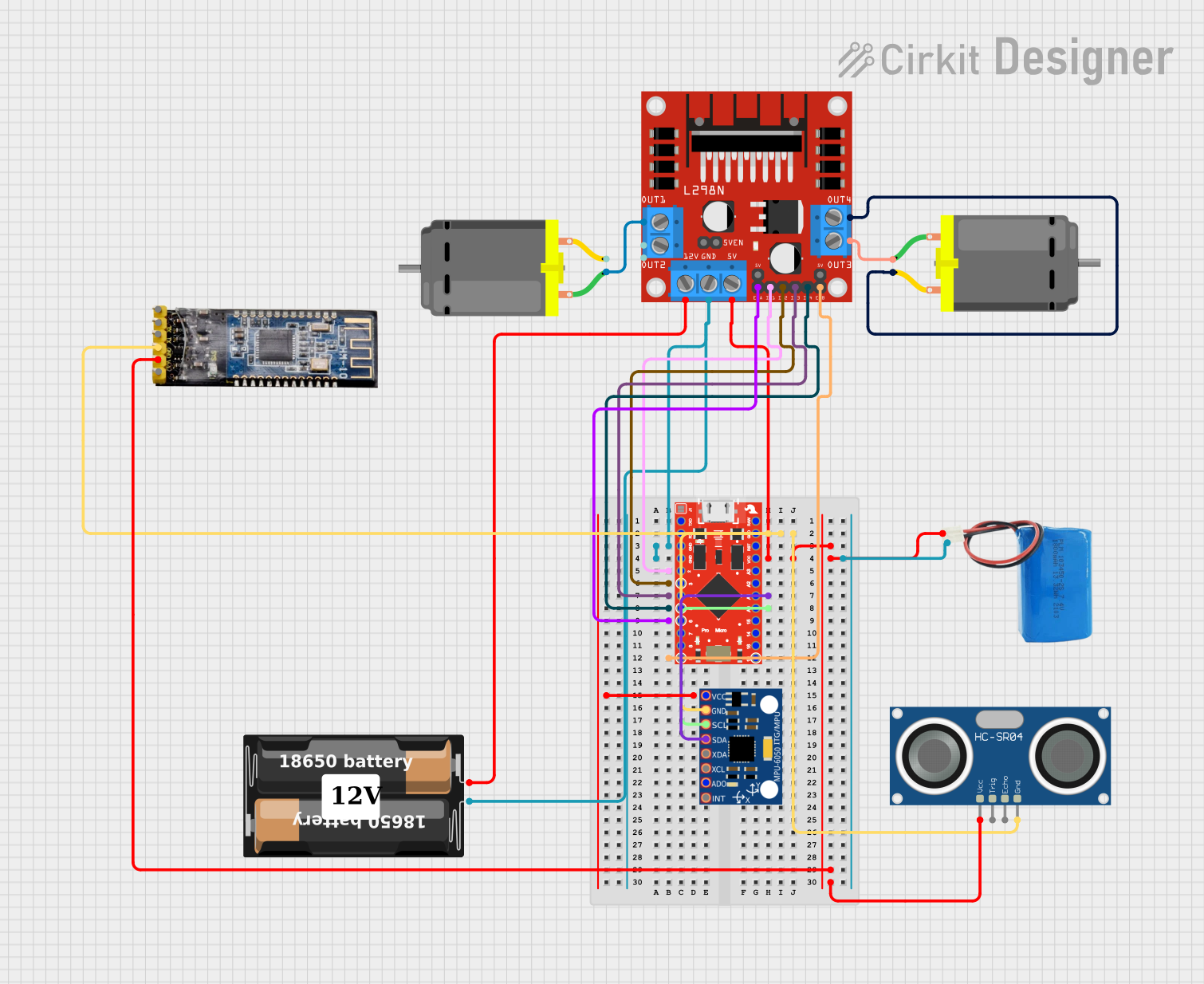
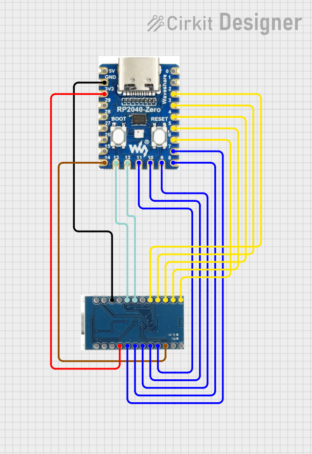
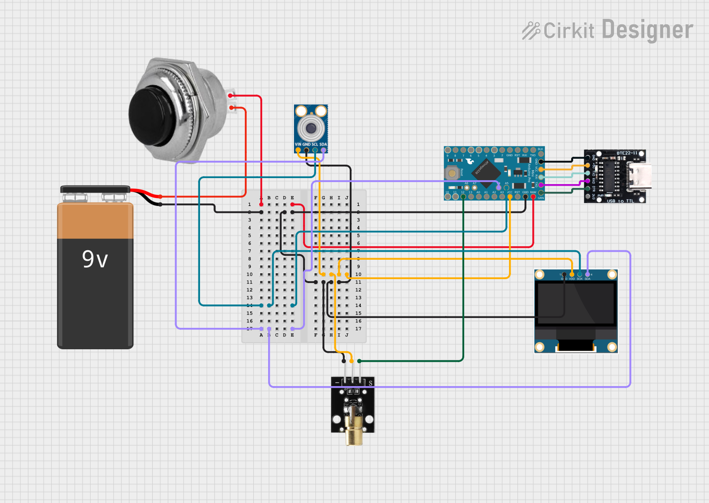
Explore Projects Built with Arduino Pro Micro
Common Applications and Use Cases
- Custom USB keyboards and mice
- Game controllers and joystick emulators
- Wearable electronics
- Compact IoT devices
- Prototyping for USB-based applications
Technical Specifications
The following table outlines the key technical details of the Arduino Pro Micro:
| Specification | Details |
|---|---|
| Microcontroller | ATmega32U4 |
| Operating Voltage | 5V |
| Input Voltage (recommended) | 7-12V |
| Input Voltage (limit) | 6-12V |
| Digital I/O Pins | 12 |
| PWM Channels | 5 |
| Analog Input Pins | 4 |
| Flash Memory | 32 KB (4 KB used by bootloader) |
| SRAM | 2.5 KB |
| EEPROM | 1 KB |
| Clock Speed | 16 MHz |
| USB Interface | Native USB |
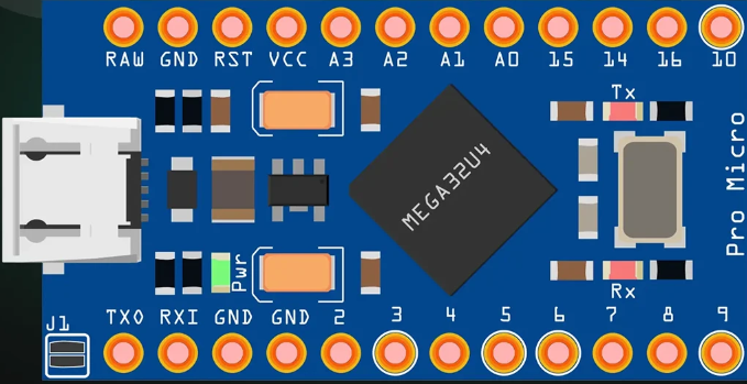
Pin Configuration and Descriptions
The Arduino Pro Micro has a total of 24 pins, including power, digital I/O, and analog input pins. Below is a detailed description of the pin configuration:
| Pin | Type | Description |
|---|---|---|
| RAW | Power Input | Unregulated power input (6-12V). |
| VCC | Power Output | Regulated 5V output. |
| GND | Ground | Ground connection. |
| RST | Reset | Resets the microcontroller. |
| TX0 | Digital Output | UART Transmit pin. |
| RX1 | Digital Input | UART Receive pin. |
| D2-D10 | Digital I/O | General-purpose digital input/output pins. |
| A0-A3 | Analog Input | Analog input pins (can also be used as digital I/O). |
| SDA | Digital I/O | I2C data line. |
| SCL | Digital I/O | I2C clock line. |
| MISO | Digital I/O | SPI Master-In-Slave-Out pin. |
| MOSI | Digital I/O | SPI Master-Out-Slave-In pin. |
| SCK | Digital I/O | SPI clock pin. |
| 3.3V | Power Output | 3.3V output (limited current). |
Usage Instructions
How to Use the Arduino Pro Micro in a Circuit
Powering the Board:
- Use the RAW pin for unregulated input voltage (6-12V).
- Alternatively, connect a regulated 5V supply to the VCC pin.
- Ensure the GND pin is connected to the ground of your circuit.
Programming the Board:
- Connect the Pro Micro to your computer using a micro-USB cable.
- Open the Arduino IDE and select "Arduino Leonardo" as the board type (the Pro Micro uses the same ATmega32U4 microcontroller).
- Write your code and upload it to the board.
Connecting Peripherals:
- Use the digital I/O pins (D2-D10) for connecting LEDs, buttons, or other digital devices.
- Use the analog input pins (A0-A3) for sensors or other analog devices.
- For I2C communication, connect your device to the SDA and SCL pins.
- For SPI communication, use the MISO, MOSI, and SCK pins.
Important Considerations and Best Practices
- USB Emulation: The Pro Micro can emulate USB devices such as keyboards or mice. Be cautious when uploading code that modifies USB behavior, as it may interfere with your ability to reprogram the board.
- Voltage Levels: Ensure that all connected devices operate at 5V logic levels to avoid damage to the board.
- Pin Limitations: Avoid exceeding the current limits of the I/O pins (40mA per pin, 200mA total for all pins combined).
Example Code: USB Keyboard Emulation
The following example demonstrates how to use the Pro Micro to emulate a USB keyboard:
#include <Keyboard.h> // Include the Keyboard library

void setup() {
  // Initialize the Keyboard library
  Keyboard.begin();
}

void loop() {
  // Send the letter 'A' every second
  Keyboard.print('A'); // Emulates pressing the 'A' key
  delay(1000);         // Wait for 1 second
}
Note: Ensure the
Keyboardlibrary is installed in your Arduino IDE. Disconnect the Pro Micro from your computer if the code causes unintended behavior.
Troubleshooting and FAQs
Common Issues and Solutions
The board is not recognized by the computer:
- Ensure the USB cable is functional and supports data transfer.
- Double-check that the correct board type (Arduino Leonardo) is selected in the Arduino IDE.
- If the board is unresponsive, try resetting it by briefly connecting the RST pin to GND.
Unable to upload code:
- Verify that the correct COM port is selected in the Arduino IDE.
- If the board is stuck in an unresponsive state, double-tap the RST pin to enter the bootloader mode and try uploading again.
USB device emulation is not working:
- Ensure the
KeyboardorMouselibrary is included in your code. - Test the board with a simple sketch to confirm it is functioning correctly.
- Ensure the
FAQs
Can the Pro Micro operate at 3.3V?
No, the Pro Micro is designed to operate at 5V. For 3.3V applications, consider using a different board, such as the Arduino Pro Mini.What is the maximum current output of the VCC pin?
The VCC pin can supply up to 500mA, depending on the input power source.How do I reset the board?
Briefly connect the RST pin to GND to reset the microcontroller.
By following this documentation, you can effectively integrate the Arduino Pro Micro into your projects and troubleshoot common issues.