How to Use F405 FC: Examples, Pinouts, and Specs
Introduction
The F405 FC is a high-performance flight controller designed for drones and other unmanned aerial vehicles (UAVs). It is built around the STM32F405 microcontroller, offering advanced processing capabilities, multiple sensor inputs, and compatibility with a wide range of peripherals. The F405 FC is ideal for applications requiring precise flight control, such as racing drones, aerial photography platforms, and autonomous UAVs. Its robust design and versatile features make it a popular choice among hobbyists and professionals alike.
Explore Projects Built with F405 FC


Explore Projects Built with F405 FC
Common Applications and Use Cases
- Racing drones for high-speed and agile flight
- Aerial photography and videography platforms
- Autonomous UAVs for mapping and surveying
- Educational and research projects involving UAVs
- Custom-built drones for specialized tasks
Technical Specifications
The F405 FC is packed with features to support a variety of UAV configurations. Below are its key technical specifications:
Key Technical Details
- Microcontroller: STM32F405 (32-bit ARM Cortex-M4, 168 MHz)
- Input Voltage: 5V to 6V (via USB or external power supply)
- IMU (Inertial Measurement Unit): MPU6000 (6-axis gyro and accelerometer)
- Flash Memory: 16 MB for blackbox logging
- UART Ports: 5 (for peripherals such as GPS, telemetry, and receivers)
- I2C Ports: 1 (for external sensors)
- PWM Outputs: 8 (for motor and servo control)
- OSD (On-Screen Display): Integrated Betaflight OSD
- BEC (Battery Eliminator Circuit): 5V/2A output
- Firmware Compatibility: Betaflight, iNav, and other open-source flight control software
- Dimensions: 36 mm x 36 mm (standard 30.5 mm x 30.5 mm mounting holes)
- Weight: ~7 grams
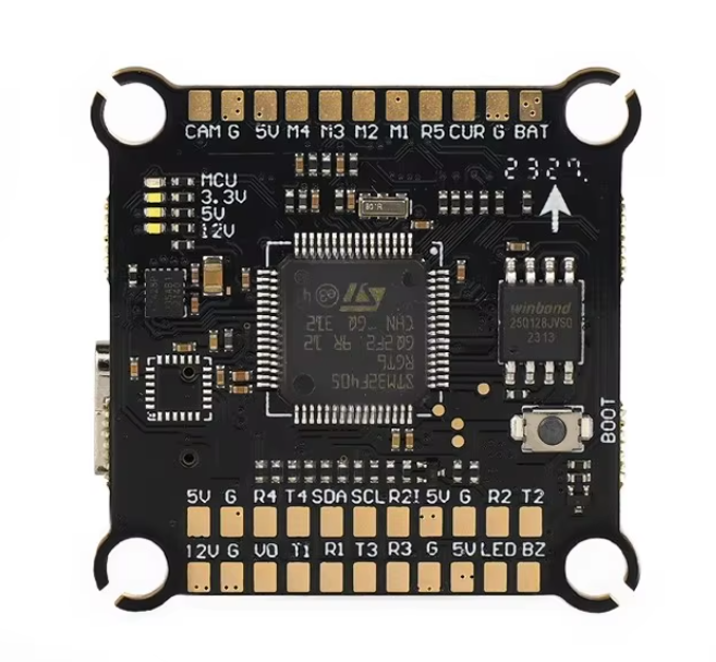
Pin Configuration and Descriptions
The F405 FC features a variety of pins for connecting peripherals and sensors. Below is the pinout description:
| Pin Name | Function | Description |
|---|---|---|
| GND | Ground | Connect to the ground of the power supply or peripherals. |
| 5V | 5V Power Output | Provides 5V output for powering peripherals (max 2A). |
| VBAT | Battery Voltage Input | Connect to the main battery for voltage monitoring. |
| M1-M8 | Motor Outputs | PWM outputs for connecting ESCs (Electronic Speed Controllers). |
| RX1-RX5 | UART Receive Pins | For connecting peripherals like GPS, telemetry modules, or receivers. |
| TX1-TX5 | UART Transmit Pins | For transmitting data to peripherals. |
| SCL, SDA | I2C Clock and Data Lines | For connecting external I2C sensors. |
| LED_STRIP | Addressable LED Output | For controlling WS2812 or similar addressable LEDs. |
| Buzzer | Buzzer Output | For connecting a piezo buzzer for audio alerts. |
| RSSI | Receiver Signal Strength Input | For monitoring the signal strength from the receiver. |
| Current | Current Sensor Input | For monitoring current draw from the battery. |
| Boot | Bootloader Mode | Used to flash firmware to the flight controller. |
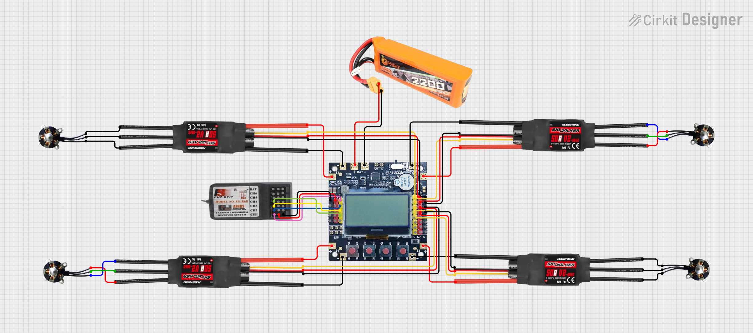
Usage Instructions
How to Use the F405 FC in a Circuit
Powering the Flight Controller:
- Connect the main battery to the VBAT pin for voltage monitoring.
- Use the 5V pin to power peripherals such as GPS modules or receivers.
- Ensure the input voltage is within the specified range (5V to 6V).
Connecting Motors and ESCs:
- Connect the signal wires of the ESCs to the M1-M8 pins.
- Ensure the motor order matches the configuration in the flight control software.
Connecting Peripherals:
- Use the UART ports (RX/TX) for GPS, telemetry, or other serial devices.
- Connect I2C sensors to the SCL and SDA pins.
Flashing Firmware:
- Use the Boot pin to enter bootloader mode.
- Flash compatible firmware (e.g., Betaflight) using a USB connection and the Betaflight Configurator.
Configuring the Flight Controller:
- Use Betaflight Configurator to set up the flight modes, PID tuning, and other parameters.
- Calibrate the IMU and configure the OSD for in-flight telemetry.
Important Considerations and Best Practices
- Power Supply: Ensure the power supply is stable and within the specified voltage range to avoid damaging the flight controller.
- Firmware Updates: Always use the latest firmware version for improved performance and bug fixes.
- ESC Calibration: Calibrate the ESCs before the first flight to ensure proper motor operation.
- Vibration Isolation: Mount the flight controller on vibration-dampening pads to reduce noise from motors and improve sensor accuracy.
- Pre-Flight Checks: Verify all connections, calibrations, and configurations before flying.
Example Code for Arduino UNO Integration
Although the F405 FC is not typically used with an Arduino UNO, you can use an Arduino to send commands or receive telemetry data via UART. Below is an example of how to communicate with the F405 FC using an Arduino:
#include <SoftwareSerial.h>

// Define RX and TX pins for SoftwareSerial
SoftwareSerial mySerial(10, 11); // RX = pin 10, TX = pin 11

void setup() {
  // Initialize serial communication
  Serial.begin(9600); // For debugging with the PC
  mySerial.begin(115200); // Communication with F405 FC

  Serial.println("Arduino is ready to communicate with F405 FC.");
}

void loop() {
  // Send a test command to the F405 FC
  mySerial.println("Hello F405 FC!");

  // Check if data is available from the F405 FC
  if (mySerial.available()) {
    String data = mySerial.readString();
    Serial.println("Received from F405 FC: " + data);
  }

  delay(1000); // Wait for 1 second before sending the next command
}
Note: Ensure the UART baud rate matches the configuration on the F405 FC.
Troubleshooting and FAQs
Common Issues and Solutions
Flight Controller Not Powering On:
- Check the power supply voltage and connections.
- Ensure the USB cable or battery is functional.
Motors Not Spinning:
- Verify motor connections to the M1-M8 pins.
- Check the ESC calibration and motor order in the flight control software.
No Communication with Betaflight Configurator:
- Ensure the correct USB drivers are installed on your computer.
- Check the USB cable for data transfer capability (some cables are power-only).
Unstable Flight or Drifting:
- Calibrate the IMU and ensure the flight controller is mounted securely.
- Check for excessive vibrations and use dampening pads if necessary.
OSD Not Displaying:
- Verify the OSD settings in the flight control software.
- Ensure the video signal is properly connected to the flight controller.
FAQs
Can I use the F405 FC with iNav firmware? Yes, the F405 FC is compatible with iNav firmware for advanced navigation features.
What is the maximum number of motors supported? The F405 FC supports up to 8 motors via PWM outputs.
How do I reset the flight controller to factory settings? Use the "Reset Settings" option in the Betaflight Configurator or flash the firmware again.
Can I connect multiple peripherals to the UART ports? Yes, but ensure each peripheral is assigned a unique UART port to avoid conflicts.
What is the purpose of the blackbox feature? The blackbox logs flight data for analysis and troubleshooting, helping to optimize performance.