
How to Use DOSonCHIP IC: Examples, Pinouts, and Specs
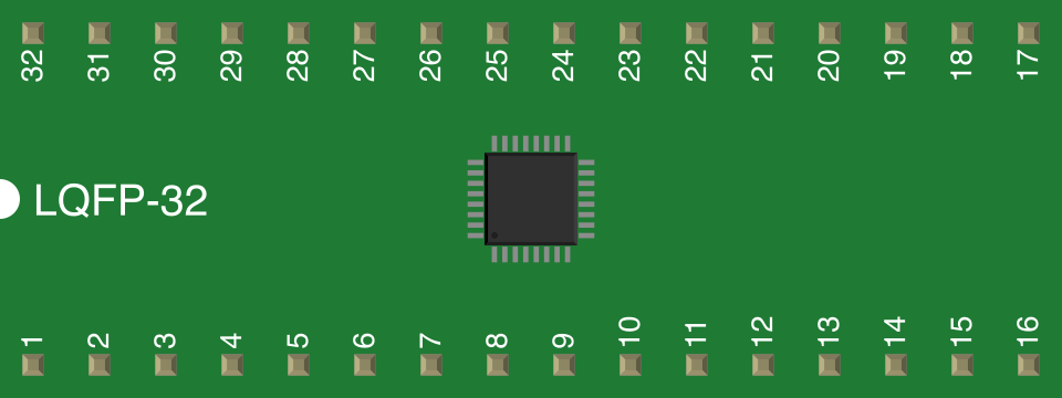
 Design with DOSonCHIP IC in Cirkit Designer
Introduction
The DOSonCHIP IC is a compact integrated circuit designed for digital signal processing (DSP). It is optimized for applications requiring high-speed data handling and low power consumption. This versatile IC is commonly used in audio processing, telecommunications, and real-time data analysis systems. Its small form factor and efficient design make it ideal for portable and embedded systems.
Explore Projects Built with DOSonCHIP IC
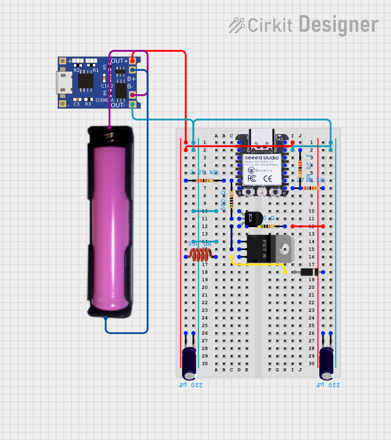 Open Project in Cirkit Designer
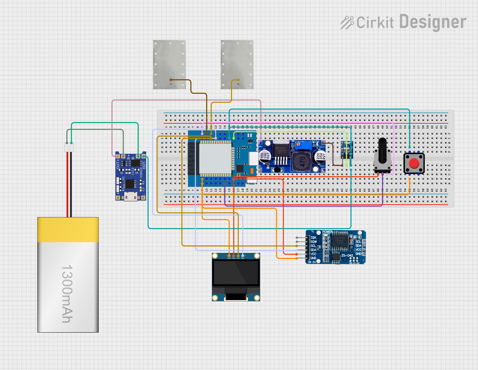 Open Project in Cirkit Designer
 Open Project in Cirkit Designer
 Open Project in Cirkit Designer
Explore Projects Built with DOSonCHIP IC
Open Project in Cirkit DesignerOpen Project in Cirkit DesignerOpen Project in Cirkit DesignerOpen Project in Cirkit DesignerCommon Applications
- Audio signal processing (e.g., equalizers, noise reduction)
- Telecommunications (e.g., modems, signal encoding/decoding)
- Real-time data analysis in IoT devices
- Image and video processing in compact systems
- Low-power embedded systems requiring DSP capabilities
Technical Specifications
Key Technical Details
| Parameter | Value |
|---|---|
| Supply Voltage (Vcc) | 1.8V to 3.3V |
| Operating Frequency | Up to 200 MHz |
| Power Consumption | < 50 mW at 3.3V |
| Data Bus Width | 16-bit |
| Operating Temperature | -40°C to +85°C |
| Package Type | QFN-32 (Quad Flat No-lead) |
Pin Configuration and Descriptions
The DOSonCHIP IC comes in a 32-pin QFN package. Below is the pin configuration:
| Pin Number | Pin Name | Description |
|---|---|---|
| 1 | VCC | Positive power supply (1.8V to 3.3V) |
| 2 | GND | Ground connection |
| 3 | CLK_IN | External clock input for synchronization |
| 4 | RESET | Active-low reset input |
| 5-12 | DATA[0:7] | 8-bit data bus for input/output |
| 13-20 | ADDR[0:7] | 8-bit address bus for memory mapping |
| 21 | RD | Active-low read enable |
| 22 | WR | Active-low write enable |
| 23 | INT | Interrupt output (active-high) |
| 24 | CS | Chip select (active-low) |
| 25-30 | GPIO[0:5] | General-purpose input/output pins |
| 31 | TEST | Test mode enable (for factory use) |
| 32 | NC | No connection |
Usage Instructions
How to Use the DOSonCHIP IC in a Circuit
- Power Supply: Connect the VCC pin to a regulated 1.8V to 3.3V power source and the GND pin to ground.
- Clock Input: Provide a stable clock signal to the CLK_IN pin. The frequency should not exceed 200 MHz.
- Reset: Use the RESET pin to initialize the IC. Pull it low momentarily during power-up.
- Data and Address Buses: Connect the DATA[0:7] and ADDR[0:7] pins to your microcontroller or processor for data transfer and memory addressing.
- Control Signals: Use the RD, WR, and CS pins to manage read/write operations and chip selection.
- Interrupt Handling: Monitor the INT pin for interrupt signals, which indicate that the IC requires attention.
- GPIO Pins: Configure the GPIO[0:5] pins as needed for additional input/output functionality.
Important Considerations
- Ensure the power supply is stable and within the specified range to avoid damage to the IC.
- Use decoupling capacitors (e.g., 0.1 µF) near the VCC pin to filter noise.
- Avoid leaving unused pins floating; connect them to ground or VCC as specified in the datasheet.
- For high-speed applications, use proper PCB layout techniques to minimize signal interference.
Example: Connecting to an Arduino UNO
The DOSonCHIP IC can be interfaced with an Arduino UNO for basic DSP tasks. Below is an example code snippet:
// Example: Interfacing DOSonCHIP IC with Arduino UNO
// This code demonstrates basic read/write operations with the IC.

#define DATA_BUS PORTD  // Define Arduino PORTD as the data bus
#define ADDR_BUS PORTC  // Define Arduino PORTC as the address bus
#define RD_PIN 8        // Define pin 8 for the RD signal
#define WR_PIN 9        // Define pin 9 for the WR signal
#define CS_PIN 10       // Define pin 10 for the CS signal

void setup() {
  // Configure data and address buses as output
  DDRD = 0xFF;  // Set PORTD (data bus) as output
  DDRC = 0xFF;  // Set PORTC (address bus) as output

  // Configure control pins as output
  pinMode(RD_PIN, OUTPUT);
  pinMode(WR_PIN, OUTPUT);
  pinMode(CS_PIN, OUTPUT);

  // Initialize control pins
  digitalWrite(RD_PIN, HIGH);  // Set RD high (inactive)
  digitalWrite(WR_PIN, HIGH);  // Set WR high (inactive)
  digitalWrite(CS_PIN, HIGH);  // Set CS high (inactive)
}

void writeData(uint8_t address, uint8_t data) {
  // Write data to the DOSonCHIP IC
  PORTC = address;           // Set address on address bus
  PORTD = data;              // Set data on data bus
  digitalWrite(CS_PIN, LOW); // Activate chip select
  digitalWrite(WR_PIN, LOW); // Activate write signal
  delayMicroseconds(1);      // Small delay for write operation
  digitalWrite(WR_PIN, HIGH);// Deactivate write signal
  digitalWrite(CS_PIN, HIGH);// Deactivate chip select
}

uint8_t readData(uint8_t address) {
  // Read data from the DOSonCHIP IC
  PORTC = address;           // Set address on address bus
  digitalWrite(CS_PIN, LOW); // Activate chip select
  digitalWrite(RD_PIN, LOW); // Activate read signal
  delayMicroseconds(1);      // Small delay for read operation
  uint8_t data = PIND;       // Read data from data bus
  digitalWrite(RD_PIN, HIGH);// Deactivate read signal
  digitalWrite(CS_PIN, HIGH);// Deactivate chip select
  return data;
}

void loop() {
  // Example usage: Write and read data
  writeData(0x01, 0x55);  // Write 0x55 to address 0x01
  uint8_t value = readData(0x01);  // Read data from address 0x01
}
Troubleshooting and FAQs
Common Issues and Solutions
No Response from the IC
- Ensure the power supply is within the specified range (1.8V to 3.3V).
- Verify that the RESET pin is properly initialized during power-up.
- Check the clock signal on the CLK_IN pin for stability and correct frequency.
Incorrect Data Read/Write
- Confirm that the data and address buses are correctly connected.
- Ensure proper timing for the RD and WR signals.
- Use pull-up or pull-down resistors on unused pins as needed.
Overheating
- Check for short circuits or excessive current draw.
- Verify that the IC is operating within the specified temperature range.
FAQs
Q: Can the DOSonCHIP IC operate without an external clock?
A: No, the IC requires a stable external clock signal on the CLK_IN pin for proper operation.
Q: What is the maximum data transfer rate?
A: The maximum data transfer rate depends on the clock frequency but can reach up to 200 Mbps.
Q: Are there any built-in power-saving modes?
A: Yes, the IC supports low-power standby modes, which can be activated via software control.
Q: Can I use the GPIO pins for PWM output?
A: No, the GPIO pins are general-purpose and do not support hardware PWM functionality.