Cirkit Designer Logo
Cirkit Designer
Your all-in-one circuit design IDE
Home / 
Component Documentation

How to Use ACS712: Examples, Pinouts, and Specs

Image of ACS712
Cirkit Designer LogoDesign with ACS712 in Cirkit Designer

Introduction

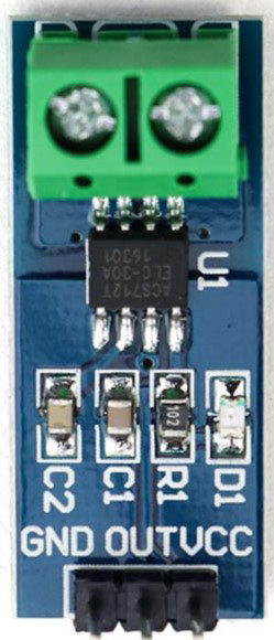
The ACS712 Hall Effect Current Sensor, manufactured by Allegro MicroSystems, is a linear current sensor designed to measure both AC and DC currents. It utilizes the Hall effect principle to provide an analog voltage output proportional to the current flowing through the sensor. The ACS712 is widely used in applications requiring current monitoring, such as motor control, power management, overcurrent protection, and energy metering. Its compact design, high accuracy, and electrical isolation make it a versatile choice for a variety of projects.

Explore Projects Built with ACS712

Use Cirkit Designer to design, explore, and prototype these projects online. Some projects support real-time simulation. Click "Open Project" to start designing instantly!
Wemos S2 Mini Controlled Smart Device with OLED Display, Thermal Printing, and RGB LED Strip
Image of DT NEA - Noah Patel: A project utilizing ACS712 in a practical application
This circuit features a Wemos S2 Mini microcontroller that controls a WS2812 RGB LED strip and communicates with a 0.96" OLED display and a 58mm mini thermal printer. The ACS712 Current Sensor is interfaced with the microcontroller to monitor current, and power is managed by a CD42 BMS connected to two 18650 Li-ion batteries, with a USB-C PD Trigger Board for power delivery. The circuit is designed for visual output (LED strip, OLED display), printing capabilities, and current sensing, likely for a portable, battery-powered monitoring and display device.
Cirkit Designer LogoOpen Project in Cirkit Designer
Arduino and GSM-Based Power Monitoring and Wi-Fi Controlled Lighting System
Image of light monitoring system: A project utilizing ACS712 in a practical application
This circuit is designed to monitor voltage and current using ACS712 current sensors and voltage sensors, calculate power, and control lighting via relay modules. It features an Arduino Uno R3 for processing sensor data and executing control logic, which includes sending alerts via a GSM module (sim 800l) if power falls below a threshold and connecting to WiFi using an ESP8266 module. The circuit also includes a battery with a charging module (TP4056), a step-up boost converter, and multiple AC power supplies with circuit breakers for safety.
Cirkit Designer LogoOpen Project in Cirkit Designer
ESP32C3 Smart Home Energy Monitor with Wi-Fi Control and LED Indicators
Image of EXTENSION: A project utilizing ACS712 in a practical application
This circuit uses an ESP32C3 microcontroller to monitor power consumption via ACS712 current and voltage sensors, control appliances through a relay, and indicate WiFi connection status with green and red LEDs. The relay can be controlled via a web interface, and the red LED indicates WiFi disconnection while the green LED indicates a successful connection.
Cirkit Designer LogoOpen Project in Cirkit Designer
ESP32-Based Power Monitoring and SMS Control System
Image of Light monitor project final: A project utilizing ACS712 in a practical application
This circuit is designed to monitor and control power consumption for two separate sets of AC loads using current and voltage sensors. It features an ESP32 microcontroller that reads sensor data to calculate power, communicates via a GSM module for remote monitoring and control, and uses a 2-channel relay to switch the loads. The system can send notifications when power consumption falls below predefined thresholds and respond to SMS commands to control the connected lights.
Cirkit Designer LogoOpen Project in Cirkit Designer

Explore Projects Built with ACS712

Use Cirkit Designer to design, explore, and prototype these projects online. Some projects support real-time simulation. Click "Open Project" to start designing instantly!
Image of DT NEA - Noah Patel: A project utilizing ACS712 in a practical application
Wemos S2 Mini Controlled Smart Device with OLED Display, Thermal Printing, and RGB LED Strip
This circuit features a Wemos S2 Mini microcontroller that controls a WS2812 RGB LED strip and communicates with a 0.96" OLED display and a 58mm mini thermal printer. The ACS712 Current Sensor is interfaced with the microcontroller to monitor current, and power is managed by a CD42 BMS connected to two 18650 Li-ion batteries, with a USB-C PD Trigger Board for power delivery. The circuit is designed for visual output (LED strip, OLED display), printing capabilities, and current sensing, likely for a portable, battery-powered monitoring and display device.
Cirkit Designer LogoOpen Project in Cirkit Designer
Image of light monitoring system: A project utilizing ACS712 in a practical application
Arduino and GSM-Based Power Monitoring and Wi-Fi Controlled Lighting System
This circuit is designed to monitor voltage and current using ACS712 current sensors and voltage sensors, calculate power, and control lighting via relay modules. It features an Arduino Uno R3 for processing sensor data and executing control logic, which includes sending alerts via a GSM module (sim 800l) if power falls below a threshold and connecting to WiFi using an ESP8266 module. The circuit also includes a battery with a charging module (TP4056), a step-up boost converter, and multiple AC power supplies with circuit breakers for safety.
Cirkit Designer LogoOpen Project in Cirkit Designer
Image of EXTENSION: A project utilizing ACS712 in a practical application
ESP32C3 Smart Home Energy Monitor with Wi-Fi Control and LED Indicators
This circuit uses an ESP32C3 microcontroller to monitor power consumption via ACS712 current and voltage sensors, control appliances through a relay, and indicate WiFi connection status with green and red LEDs. The relay can be controlled via a web interface, and the red LED indicates WiFi disconnection while the green LED indicates a successful connection.
Cirkit Designer LogoOpen Project in Cirkit Designer
Image of Light monitor project final: A project utilizing ACS712 in a practical application
ESP32-Based Power Monitoring and SMS Control System
This circuit is designed to monitor and control power consumption for two separate sets of AC loads using current and voltage sensors. It features an ESP32 microcontroller that reads sensor data to calculate power, communicates via a GSM module for remote monitoring and control, and uses a 2-channel relay to switch the loads. The system can send notifications when power consumption falls below predefined thresholds and respond to SMS commands to control the connected lights.
Cirkit Designer LogoOpen Project in Cirkit Designer

Technical Specifications

The following are the key technical details of the ACS712 Hall Effect Current Sensor:

  • Manufacturer Part ID: ACS712
  • Supply Voltage (Vcc): 4.5V to 5.5V
  • Current Measurement Range:
    • ACS712-05B: ±5A
    • ACS712-20A: ±20A
    • ACS712-30A: ±30A
  • Sensitivity:
    • ACS712-05B: 185 mV/A
    • ACS712-20A: 100 mV/A
    • ACS712-30A: 66 mV/A
  • Output Voltage: Analog, centered at Vcc/2 (2.5V for 5V supply)
  • Bandwidth: 80 kHz
  • Response Time: 5 µs
  • Isolation Voltage: 2.1 kV RMS
  • Operating Temperature Range: -40°C to 85°C

Pin Configuration and Descriptions

The ACS712 is typically available in an 8-pin SOIC package. Below is the pin configuration:

Pin Number Pin Name Description
1 IP+ Positive current input terminal (connect to the load or current source).
2 IP- Negative current input terminal (connect to the return path of the load).
3 NC Not connected (leave unconnected).
4 GND Ground (connect to the system ground).
5 VIOUT Analog output voltage proportional to the measured current.
6 NC Not connected (leave unconnected).
7 Vcc Supply voltage (4.5V to 5.5V, typically 5V).
8 NC Not connected (leave unconnected).

Usage Instructions

How to Use the ACS712 in a Circuit

  1. Power Supply: Connect the Vcc pin to a 5V power supply and the GND pin to the system ground.
  2. Current Path: Connect the current-carrying conductor to the IP+ and IP- pins. Ensure the current flows in the correct direction as indicated on the sensor.
  3. Output Signal: The VIOUT pin provides an analog voltage proportional to the current. At 0A, the output voltage is approximately 2.5V (for a 5V supply). The voltage increases or decreases linearly with the current.
  4. Load Resistor: If required, connect a pull-down resistor to stabilize the output signal.

Important Considerations and Best Practices

  • Isolation: The ACS712 provides electrical isolation between the current-carrying conductor and the output signal, making it safe for high-voltage applications.
  • Filtering: To reduce noise, connect a capacitor (e.g., 0.1 µF) between the VIOUT pin and GND.
  • Calibration: For accurate measurements, calibrate the sensor by measuring the output voltage at 0A and adjusting for any offset.
  • Current Range: Choose the appropriate ACS712 variant (05B, 20A, or 30A) based on the maximum current in your application.
  • Heat Dissipation: Avoid exceeding the maximum current rating to prevent overheating.

Example: Using ACS712 with Arduino UNO

Below is an example of how to interface the ACS712 with an Arduino UNO to measure current:

// Include necessary libraries (if any)

// Define the analog pin connected to the ACS712 VIOUT pin
const int sensorPin = A0;

// Define the sensitivity of the ACS712 (e.g., 185 mV/A for ACS712-05B)
const float sensitivity = 0.185; // Sensitivity in V/A

// Define the supply voltage (Vcc) and the zero-current voltage (Vcc/2)
const float Vcc = 5.0; // Supply voltage in volts
const float zeroCurrentVoltage = Vcc / 2; // Zero-current output voltage

void setup() {
  Serial.begin(9600); // Initialize serial communication
}

void loop() {
  // Read the analog value from the sensor
  int sensorValue = analogRead(sensorPin);

  // Convert the analog value to voltage
  float sensorVoltage = (sensorValue / 1023.0) * Vcc;

  // Calculate the current in amperes
  float current = (sensorVoltage - zeroCurrentVoltage) / sensitivity;

  // Print the current to the Serial Monitor
  Serial.print("Current: ");
  Serial.print(current);
  Serial.println(" A");

  delay(1000); // Wait for 1 second before the next reading
}

Troubleshooting and FAQs

Common Issues and Solutions

  1. No Output or Incorrect Readings:

    • Ensure the Vcc and GND pins are properly connected to a 5V power supply and ground.
    • Verify that the current-carrying conductor is connected to the IP+ and IP- pins.
  2. High Noise in Output Signal:

    • Add a capacitor (e.g., 0.1 µF) between the VIOUT pin and GND to filter out noise.
    • Use shielded cables for the current-carrying conductor to reduce electromagnetic interference.
  3. Output Voltage Does Not Return to 2.5V at 0A:

    • Calibrate the sensor by measuring the output voltage at 0A and adjusting for any offset in your calculations.
  4. Overheating:

    • Ensure the current flowing through the sensor does not exceed its maximum rating.
    • Use proper heat dissipation techniques if the sensor is operating near its maximum current limit.

FAQs

Q1: Can the ACS712 measure both AC and DC currents?
A1: Yes, the ACS712 can measure both AC and DC currents. The output voltage varies linearly with the current in both cases.

Q2: How do I choose the right ACS712 variant for my application?
A2: Select the variant based on the maximum current you need to measure:

  • ACS712-05B: ±5A
  • ACS712-20A: ±20A
  • ACS712-30A: ±30A

Q3: What is the accuracy of the ACS712?
A3: The ACS712 has a typical accuracy of ±1.5% at 25°C. However, accuracy may vary with temperature and other factors.

Q4: Can I use the ACS712 with a 3.3V microcontroller?
A4: Yes, but you need to ensure the output voltage range of the ACS712 is compatible with the ADC input range of your microcontroller.