How to Use esp32-c3 mini-1: Examples, Pinouts, and Specs
Introduction
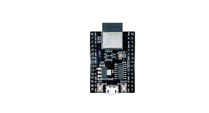
The ESP32-C3 Mini-1 is a compact, low-power microcontroller module with integrated Wi-Fi and Bluetooth Low Energy (BLE) capabilities. It is based on the RISC-V architecture, offering high efficiency and performance for a wide range of applications. This module is specifically designed for Internet of Things (IoT) applications, enabling seamless wireless connectivity and control. Its small form factor and versatile GPIO pins make it ideal for projects requiring compact designs and reliable wireless communication.
Explore Projects Built with esp32-c3 mini-1


Explore Projects Built with esp32-c3 mini-1
Common Applications and Use Cases
- Smart home devices (e.g., smart plugs, light switches)
- Wearable electronics
- Industrial IoT systems
- Wireless sensors and data loggers
- Remote monitoring and control systems
- Prototyping and development of connected devices
Technical Specifications
Key Technical Details
| Parameter | Specification |
|---|---|
| Microcontroller | RISC-V single-core processor |
| Clock Speed | Up to 160 MHz |
| Flash Memory | 4 MB (embedded) |
| RAM | 400 KB |
| Wi-Fi | IEEE 802.11 b/g/n (2.4 GHz) |
| Bluetooth | Bluetooth 5.0 Low Energy (BLE) |
| Operating Voltage | 3.0V to 3.6V |
| GPIO Pins | 15 (multipurpose) |
| Communication Interfaces | UART, SPI, I2C, I2S, PWM |
| Power Consumption | Ultra-low power in deep sleep mode |
| Dimensions | 16.6 mm x 13.2 mm x 2.4 mm |
Pin Configuration and Descriptions
| Pin Number | Pin Name | Description |
|---|---|---|
| 1 | GND | Ground |
| 2 | 3V3 | 3.3V Power Supply |
| 3 | GPIO0 | General-purpose I/O, boot mode selection |
| 4 | GPIO1 | General-purpose I/O |
| 5 | GPIO2 | General-purpose I/O |
| 6 | GPIO3 | General-purpose I/O |
| 7 | GPIO4 | General-purpose I/O |
| 8 | GPIO5 | General-purpose I/O |
| 9 | GPIO6 | General-purpose I/O |
| 10 | GPIO7 | General-purpose I/O |
| 11 | GPIO8 | General-purpose I/O |
| 12 | GPIO9 | General-purpose I/O |
| 13 | GPIO10 | General-purpose I/O |
| 14 | GPIO11 | General-purpose I/O |
| 15 | EN | Enable pin (active high) |
Usage Instructions
How to Use the ESP32-C3 Mini-1 in a Circuit
- Power Supply: Connect the 3V3 pin to a 3.3V power source and the GND pin to ground.
- Boot Mode: To enter programming mode, connect GPIO0 to GND during reset.
- GPIO Usage: Use the GPIO pins for interfacing with sensors, actuators, or other peripherals. Configure the pins as input or output in your code.
- Communication Interfaces: Use UART, SPI, or I2C for communication with other devices. Ensure proper pull-up resistors for I2C lines if required.
- Programming: Use the Arduino IDE or ESP-IDF (Espressif IoT Development Framework) to program the module.
Important Considerations and Best Practices
- Voltage Levels: Ensure all connected peripherals operate at 3.3V logic levels to avoid damaging the module.
- Antenna Placement: Avoid placing metal objects near the module's antenna to ensure optimal Wi-Fi and Bluetooth performance.
- Deep Sleep Mode: Use deep sleep mode to minimize power consumption in battery-powered applications.
- Firmware Updates: Regularly update the firmware to benefit from the latest features and security patches.
Example Code for Arduino UNO Integration
Below is an example of using the ESP32-C3 Mini-1 to control an LED via Wi-Fi:
#include <WiFi.h> // Include the Wi-Fi library

const char* ssid = "Your_SSID";       // Replace with your Wi-Fi SSID
const char* password = "Your_PASSWORD"; // Replace with your Wi-Fi password

const int ledPin = 2; // GPIO2 is connected to the LED

void setup() {
  pinMode(ledPin, OUTPUT); // Set GPIO2 as an output
  Serial.begin(115200);    // Initialize serial communication

  // Connect to Wi-Fi
  Serial.print("Connecting to Wi-Fi...");
  WiFi.begin(ssid, password);
  while (WiFi.status() != WL_CONNECTED) {
    delay(500);
    Serial.print(".");
  }
  Serial.println("\nWi-Fi connected!");
}

void loop() {
  digitalWrite(ledPin, HIGH); // Turn the LED on
  delay(1000);                // Wait for 1 second
  digitalWrite(ledPin, LOW);  // Turn the LED off
  delay(1000);                // Wait for 1 second
}
Troubleshooting and FAQs
Common Issues and Solutions
Wi-Fi Connection Fails:
- Ensure the SSID and password are correct.
- Check if the router is within range and functioning properly.
- Verify that the module's antenna is not obstructed.
Module Does Not Respond:
- Confirm that the power supply provides a stable 3.3V.
- Check the connections to the EN and GPIO0 pins.
- Ensure the correct COM port is selected in the programming environment.
GPIO Pins Not Working:
- Verify the pin mode configuration in the code (input/output).
- Check for short circuits or incorrect wiring.
High Power Consumption:
- Use deep sleep mode when the module is idle.
- Minimize the use of peripherals that consume significant power.
FAQs
Q: Can the ESP32-C3 Mini-1 operate at 5V?
A: No, the module operates at 3.3V. Connecting it to 5V may damage the module.
Q: How do I reset the module?
A: Pull the EN pin low momentarily to reset the module.
Q: Can I use the ESP32-C3 Mini-1 with the Arduino IDE?
A: Yes, the module is compatible with the Arduino IDE. Install the ESP32 board package to get started.
Q: Does the module support OTA (Over-the-Air) updates?
A: Yes, the ESP32-C3 Mini-1 supports OTA updates, allowing you to update firmware wirelessly.