Cirkit Designer Logo
Cirkit Designer
Your all-in-one circuit design IDE
Home / 
Component Documentation

How to Use ESP32 C6 DEVKITC 1: Examples, Pinouts, and Specs

Image of ESP32 C6 DEVKITC 1
Cirkit Designer LogoDesign with ESP32 C6 DEVKITC 1 in Cirkit Designer

Introduction

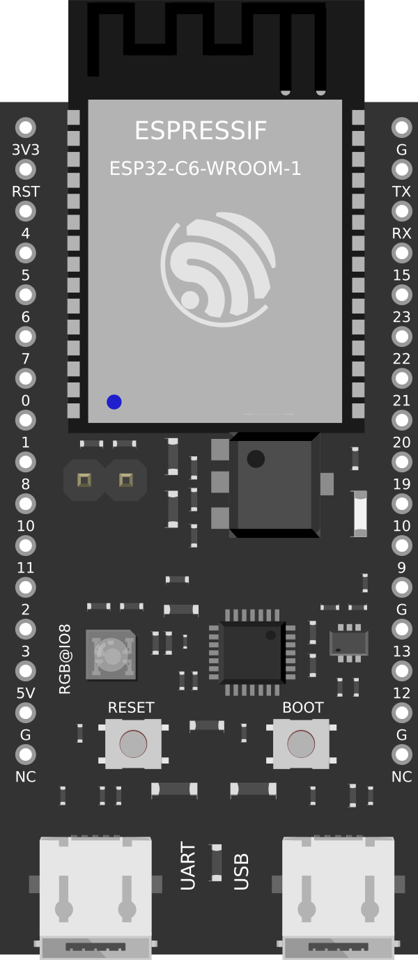
The ESP32-C6 DEVKITC-1 is a development board created by Espressif Systems, featuring the ESP32-C6 SoC (System on Chip). This SoC is a highly-integrated, low-power Wi-Fi 6 and Bluetooth 5 (LE) solution that is ideal for Internet of Things (IoT) and smart home applications. The dual-core processor and advanced hardware security features make it a versatile platform for developers looking to build connected devices with robust performance and security.

Explore Projects Built with ESP32 C6 DEVKITC 1

Use Cirkit Designer to design, explore, and prototype these projects online. Some projects support real-time simulation. Click "Open Project" to start designing instantly!
ESP32-Based Environmental Monitoring and Alert System with Solar Charging
Image of mark: A project utilizing ESP32 C6 DEVKITC 1 in a practical application
This circuit features an ESP32 Devkit V1 microcontroller connected to various sensors and modules for monitoring and communication purposes. It includes an MQ-2 gas sensor and a DHT11 temperature and humidity sensor, both interfaced with the ESP32 for environmental data collection. The circuit is powered by a 12V battery, regulated to 5V by step-down converters, and includes a solar charge controller connected to a solar panel for battery charging, a UPS module for power management, and a SIM900A module for GSM communication. Additionally, there is a WS2812 RGB LED strip for visual feedback and a piezo buzzer for audio alerts, both controlled by the ESP32.
Cirkit Designer LogoOpen Project in Cirkit Designer
ESP32-Based Smart Weather and Health Monitoring System with Wi-Fi Connectivity
Image of Health Monitoring System: A project utilizing ESP32 C6 DEVKITC 1 in a practical application
This circuit uses an ESP32 Devkit V1 microcontroller to interface with multiple sensors, including a DHT11 temperature and humidity sensor, a DS18B20 temperature sensor, and a MAX30102 pulse oximeter and heart-rate sensor. The ESP32 reads data from these sensors and can process or transmit the information for further use.
Cirkit Designer LogoOpen Project in Cirkit Designer
ESP32-Based Environmental Monitoring and Alert System with Solar Charging
Image of Schematic: A project utilizing ESP32 C6 DEVKITC 1 in a practical application
This circuit features an ESP32 Devkit V1 microcontroller connected to various sensors and devices, including a DHT11 temperature and humidity sensor, an MQ-2 gas sensor, and a WS2812 RGB LED strip. The ESP32 controls the LED strip and processes sensor readings, while a SIM900A module provides cellular communication capabilities. Power management is handled by a UPS module fed by a 12V battery charged via a solar panel and charge controller, with voltage regulation provided by step-down converters. Additionally, a piezo buzzer is included for audible alerts, and the system's safety is ensured by a circuit breaker connected to a switching power supply for AC to DC conversion.
Cirkit Designer LogoOpen Project in Cirkit Designer
ESP32-Based Smart Agriculture System with LoRa Communication
Image of Soil Monitoring Device: A project utilizing ESP32 C6 DEVKITC 1 in a practical application
This circuit features an ESP32 Devkit V1 microcontroller as the central processing unit, interfacing with various sensors including a PH Meter, an NPK Soil Sensor, and a Soil Moisture Sensor for environmental data collection. It also includes an EBYTE LoRa E220 module for wireless communication. Power management is handled by a Step Up Boost Power Converter, which is connected to a 12V Battery, stepping up the voltage to power the ESP32 and sensors, with common ground connections throughout the circuit.
Cirkit Designer LogoOpen Project in Cirkit Designer

Explore Projects Built with ESP32 C6 DEVKITC 1

Use Cirkit Designer to design, explore, and prototype these projects online. Some projects support real-time simulation. Click "Open Project" to start designing instantly!
Image of mark: A project utilizing ESP32 C6 DEVKITC 1 in a practical application
ESP32-Based Environmental Monitoring and Alert System with Solar Charging
This circuit features an ESP32 Devkit V1 microcontroller connected to various sensors and modules for monitoring and communication purposes. It includes an MQ-2 gas sensor and a DHT11 temperature and humidity sensor, both interfaced with the ESP32 for environmental data collection. The circuit is powered by a 12V battery, regulated to 5V by step-down converters, and includes a solar charge controller connected to a solar panel for battery charging, a UPS module for power management, and a SIM900A module for GSM communication. Additionally, there is a WS2812 RGB LED strip for visual feedback and a piezo buzzer for audio alerts, both controlled by the ESP32.
Cirkit Designer LogoOpen Project in Cirkit Designer
Image of Health Monitoring System: A project utilizing ESP32 C6 DEVKITC 1 in a practical application
ESP32-Based Smart Weather and Health Monitoring System with Wi-Fi Connectivity
This circuit uses an ESP32 Devkit V1 microcontroller to interface with multiple sensors, including a DHT11 temperature and humidity sensor, a DS18B20 temperature sensor, and a MAX30102 pulse oximeter and heart-rate sensor. The ESP32 reads data from these sensors and can process or transmit the information for further use.
Cirkit Designer LogoOpen Project in Cirkit Designer
Image of Schematic: A project utilizing ESP32 C6 DEVKITC 1 in a practical application
ESP32-Based Environmental Monitoring and Alert System with Solar Charging
This circuit features an ESP32 Devkit V1 microcontroller connected to various sensors and devices, including a DHT11 temperature and humidity sensor, an MQ-2 gas sensor, and a WS2812 RGB LED strip. The ESP32 controls the LED strip and processes sensor readings, while a SIM900A module provides cellular communication capabilities. Power management is handled by a UPS module fed by a 12V battery charged via a solar panel and charge controller, with voltage regulation provided by step-down converters. Additionally, a piezo buzzer is included for audible alerts, and the system's safety is ensured by a circuit breaker connected to a switching power supply for AC to DC conversion.
Cirkit Designer LogoOpen Project in Cirkit Designer
Image of Soil Monitoring Device: A project utilizing ESP32 C6 DEVKITC 1 in a practical application
ESP32-Based Smart Agriculture System with LoRa Communication
This circuit features an ESP32 Devkit V1 microcontroller as the central processing unit, interfacing with various sensors including a PH Meter, an NPK Soil Sensor, and a Soil Moisture Sensor for environmental data collection. It also includes an EBYTE LoRa E220 module for wireless communication. Power management is handled by a Step Up Boost Power Converter, which is connected to a 12V Battery, stepping up the voltage to power the ESP32 and sensors, with common ground connections throughout the circuit.
Cirkit Designer LogoOpen Project in Cirkit Designer

Common Applications and Use Cases

  • Smart home devices (e.g., lighting, security systems)
  • IoT sensor networks
  • Wearable electronics
  • Wireless control and monitoring systems
  • Energy management solutions

Technical Specifications

Key Technical Details

  • CPU: Dual-core 32-bit processor
  • Wi-Fi: IEEE 802.11ax (Wi-Fi 6)
  • Bluetooth: Bluetooth 5 (LE)
  • RAM: TBD
  • Flash Memory: TBD
  • GPIOs: TBD
  • Operating Voltage: 3.3V
  • I/O Voltage: 3.3V

Pin Configuration and Descriptions

Pin Number Name Description
1 3V3 3.3V power supply input
2 GND Ground
3 EN Chip enable. Active high.
... ... ...
n IOx General purpose IO pin x

Note: The pin configuration table should be completed with actual pin numbers and descriptions based on the specific ESP32-C6 DEVKITC-1 board layout.

Usage Instructions

How to Use the Component in a Circuit

  1. Power Supply: Ensure that the board is powered with a stable 3.3V supply. Exceeding the voltage rating may damage the board.

  2. Programming: Use the provided USB interface to program the board with the desired firmware. The ESP32-C6 is compatible with the ESP-IDF development framework.

  3. GPIO Configuration: Configure the GPIO pins according to your application needs. The pins can be set as input or output using software.

  4. Wi-Fi and Bluetooth Setup: Utilize the ESP-IDF or Arduino IDE to configure and enable Wi-Fi and Bluetooth functionalities.

Important Considerations and Best Practices

  • Always check the power supply and I/O pin voltage levels to prevent damage.
  • Use proper ESD precautions when handling the board to avoid static damage.
  • Ensure that antenna considerations are met for optimal wireless performance.
  • Follow the Espressif programming guide for software setup and development.

Troubleshooting and FAQs

Common Issues

  • Board not powering up: Check the power supply connections and voltage levels.
  • Failure to connect to Wi-Fi or Bluetooth: Ensure the antenna is properly connected and not obstructed.
  • Programming errors: Verify the correct drivers are installed and the board is selected in the IDE.

Solutions and Tips for Troubleshooting

  • Double-check wiring and solder joints for any loose connections or shorts.
  • Use serial output to debug and monitor the board's status during programming.
  • Consult the Espressif forums and community for support on specific issues.

Example Code for Arduino UNO Connection

#include <WiFi.h>

// Replace with your network credentials
const char* ssid = "your_SSID";
const char* password = "your_PASSWORD";

void setup() {
  Serial.begin(115200);
  
  // Connect to Wi-Fi
  WiFi.begin(ssid, password);
  while (WiFi.status() != WL_CONNECTED) {
    delay(500);
    Serial.println("Connecting to WiFi...");
  }
  Serial.println("Connected to WiFi");
}

void loop() {
  // Your code here
}

Note: This example assumes that the ESP32-C6 DEVKITC-1 is programmed using the Arduino IDE with the appropriate board support package installed.

Code Comments

  • The WiFi.h library is included to enable Wi-Fi functionality.
  • Replace your_SSID and your_PASSWORD with your actual Wi-Fi credentials.
  • The Serial.begin(115200); initializes serial communication at 115200 baud rate.
  • WiFi.begin(ssid, password); starts the connection to the Wi-Fi network.
  • The while loop waits until the ESP32-C6 is connected to the Wi-Fi network before proceeding.
  • Serial.println("Connected to WiFi"); prints a confirmation message once connected.

Remember to adhere to the 80 character line length limit for code comments, wrapping text as necessary.