How to Use sparkfun-samd21-mini-breakout: Examples, Pinouts, and Specs
Introduction
The SparkFun SAMD21 Mini Breakout is a compact and versatile development board that harnesses the power of the Microchip ATSAMD21G18, a 32-bit ARM Cortex-M0+ microcontroller. With a rich set of peripherals and a minimalistic design, this breakout board is ideal for a wide range of applications including IoT devices, wearables, and high-performance embedded systems.
Explore Projects Built with sparkfun-samd21-mini-breakout

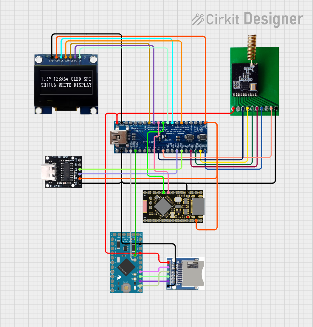
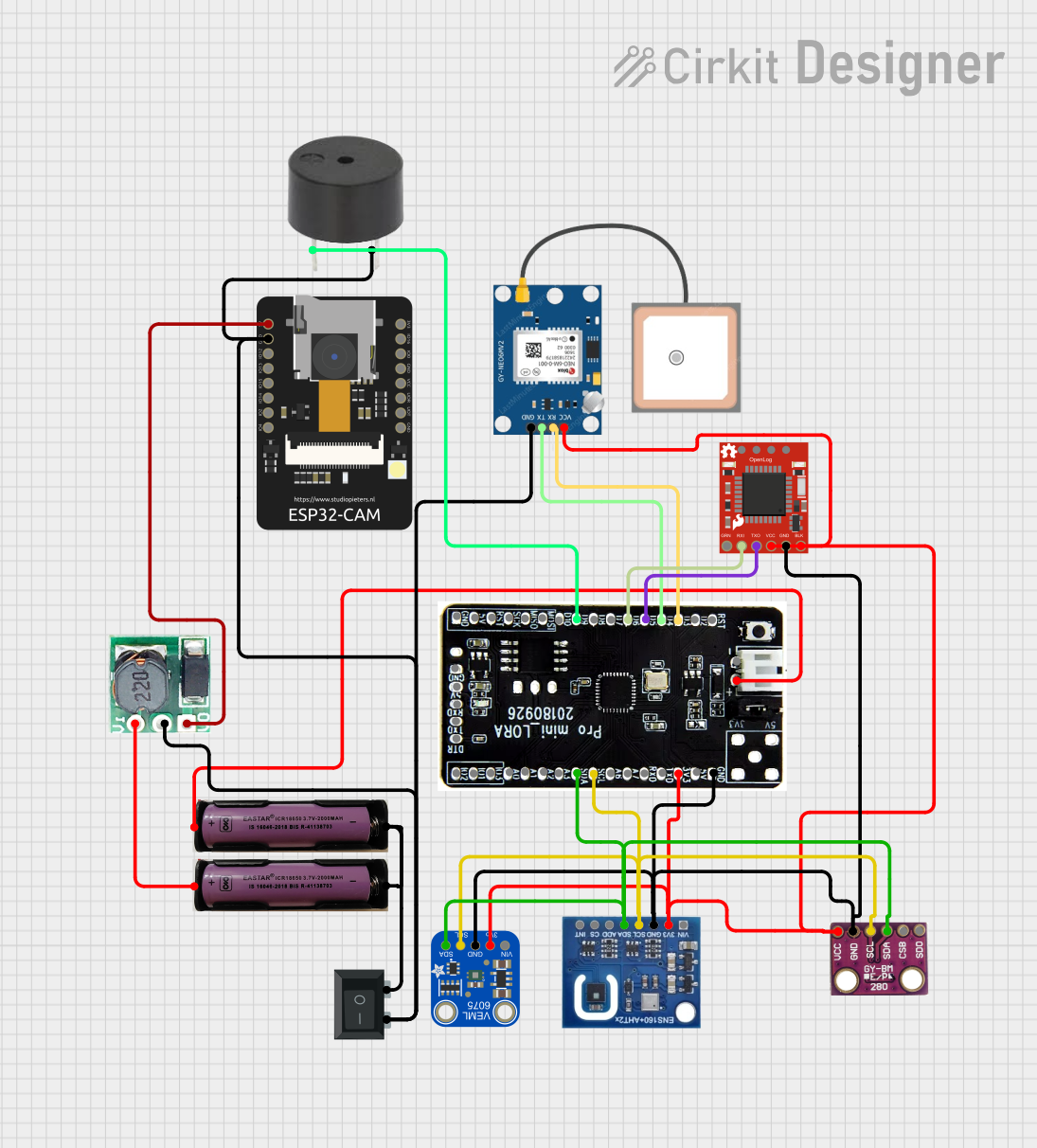

Explore Projects Built with sparkfun-samd21-mini-breakout
Common Applications and Use Cases
- Prototyping IoT devices
- Wearable technology
- Low-power sensor networks
- Educational platforms for electronics and programming
- Battery-powered applications
- Rapid development of embedded systems
Technical Specifications
The SparkFun SAMD21 Mini Breakout offers a balance of performance and power efficiency, making it suitable for a variety of projects.
Key Technical Details
- Microcontroller: ATSAMD21G18, 32-bit ARM Cortex-M0+
- Operating Voltage: 3.3V
- Input Voltage: 5V (via USB) or 3.3V to 6V (via VIN pin)
- Digital I/O Pins: 20
- PWM Channels: 10
- Analog Input Channels: 6 (12-bit ADC)
- Analog Output Channels: 1 (10-bit DAC)
- Flash Memory: 256KB
- SRAM: 32KB
- Clock Speed: 48MHz
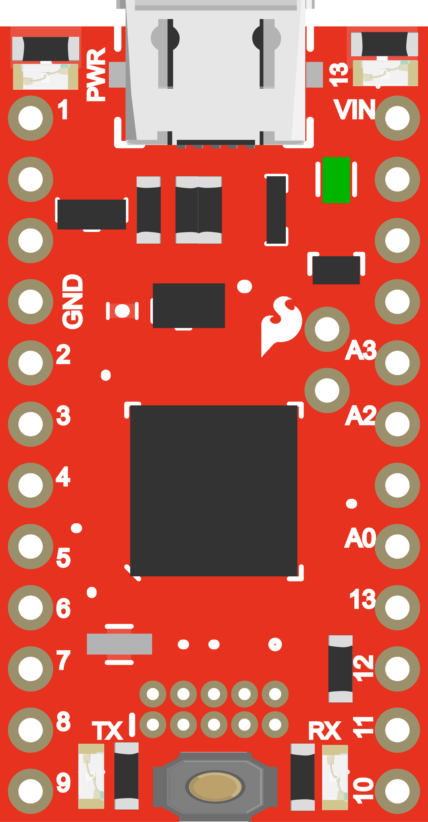
Pin Configuration and Descriptions
| Pin Number | Function | Description |
|---|---|---|
| 1 | VIN | Supply voltage input (3.3V to 6V) |
| 2 | GND | Ground |
| 3-5 | Digital I/O | General-purpose input/output |
| 6 | AREF | Analog reference voltage for ADC |
| 7-12 | Analog Input | Analog input channels for ADC |
| 13 | RESET | Reset pin (active low) |
| 14-19 | Digital I/O | General-purpose input/output with PWM capability |
| 20 | USB | USB interface for programming and power |
Usage Instructions
How to Use the Component in a Circuit
- Powering the Board: Connect the USB cable for power and programming or supply voltage to the VIN pin for standalone operation.
- Programming: Use the Arduino IDE or other compatible software to upload code to the board via the USB connection.
- I/O Pin Usage: Configure the pins as input or output according to your application needs using the appropriate software commands.
- Analog Reading: Connect sensors to the analog input pins and use the ADC functionalities to read analog values.
- PWM Outputs: Utilize PWM-capable pins to control actuators like motors or dim LEDs.
Important Considerations and Best Practices
- Always ensure that the power supply voltage does not exceed the recommended range.
- When using the board in standalone mode, ensure that the power supply is stable and regulated.
- Avoid exposing the board to static electricity or physical stress to prevent damage.
- Use proper decoupling capacitors close to the board's power supply pins to minimize noise.
- Ensure that the I/O pins are not subjected to voltages higher than 3.3V to prevent damage.
Troubleshooting and FAQs
Common Issues Users Might Face
- Board not recognized by the computer: Check the USB cable and connections. Ensure that the correct drivers are installed.
- Failure to upload code: Verify the selected board and port in the Arduino IDE. Ensure the bootloader is functioning correctly.
- Unexpected behavior in circuits: Double-check wiring and ensure that the code corresponds to the correct pin assignments.
Solutions and Tips for Troubleshooting
- If the board is not recognized, try a different USB cable or port and reset the board.
- For upload issues, ensure that no other program is using the same COM port.
- Use serial debugging to check for errors in the code and monitor the behavior of the board.
FAQs
Q: Can I use the Arduino IDE with the SparkFun SAMD21 Mini Breakout?
A: Yes, the board is compatible with the Arduino IDE. You will need to install the appropriate board definitions for the SAMD21.
Q: What is the maximum current that the I/O pins can source or sink?
A: The maximum current per I/O pin is 7 mA. It's important not to exceed this limit to prevent damage to the microcontroller.
Q: Is there onboard voltage regulation?
A: Yes, the board includes a 3.3V regulator. When powering via VIN, the input voltage is regulated down to the operating voltage.
Example Code for Arduino UNO
Below is a simple example of how to blink an LED connected to pin 13 of the SparkFun SAMD21 Mini Breakout using the Arduino IDE.
// Pin 13 has an LED connected on most Arduino boards.
int led = 13;

// the setup routine runs once when you press reset:
void setup() {
  // initialize the digital pin as an output.
  pinMode(led, OUTPUT);
}

// the loop routine runs over and over again forever:
void loop() {
  digitalWrite(led, HIGH);   // turn the LED on (HIGH is the voltage level)
  delay(1000);               // wait for a second
  digitalWrite(led, LOW);    // turn the LED off by making the voltage LOW
  delay(1000);               // wait for a second
}
Remember to select the correct board from the Tools > Board menu in the Arduino IDE before uploading the code to the SparkFun SAMD21 Mini Breakout.
This documentation provides a comprehensive guide to getting started with the SparkFun SAMD21 Mini Breakout. For further assistance, consult the SparkFun forums and the extensive online resources available.