Cirkit Designer Logo
Cirkit Designer
Your all-in-one circuit design IDE
Home / 
Component Documentation

How to Use LS-BIDI-4: Examples, Pinouts, and Specs

Image of LS-BIDI-4
Cirkit Designer LogoDesign with LS-BIDI-4 in Cirkit Designer

Introduction

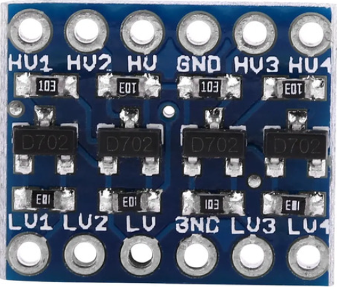
The LS-BIDI-4 is a bidirectional level shifter designed to enable communication between devices operating at different voltage levels. It is commonly used to bridge the gap between 3.3V and 5V systems, ensuring seamless data transfer in both directions. This component is particularly useful for interfacing microcontrollers, sensors, and other peripherals with varying voltage requirements. Its compact design and reliable performance make it a popular choice in embedded systems and IoT applications.

Explore Projects Built with LS-BIDI-4

Use Cirkit Designer to design, explore, and prototype these projects online. Some projects support real-time simulation. Click "Open Project" to start designing instantly!
Battery-Powered Adjustable Voltage Regulator with Li-ion 18650 Batteries and BMS
Image of mini ups: A project utilizing LS-BIDI-4 in a practical application
This circuit is a power management system that uses four Li-ion 18650 batteries connected to a 2S 30A BMS for battery management and protection. The system includes step-up and step-down voltage regulators to provide adjustable output voltages, controlled by a rocker switch, and multiple DC jacks for power input and output.
Cirkit Designer LogoOpen Project in Cirkit Designer
18650 Li-ion Battery Pack with BMS for 5V Power Supply
Image of battary: A project utilizing LS-BIDI-4 in a practical application
This circuit consists of a battery management system (BMS) connected to a series of 18650 Li-ion batteries arranged in a 4S configuration to provide a regulated output voltage. The BMS ensures safe charging and discharging of the batteries, while a connector provides a 5V output for external devices.
Cirkit Designer LogoOpen Project in Cirkit Designer
Satellite-Based Timing and Navigation System with SDR and Atomic Clock Synchronization
Image of GPS 시스템 측정 구성도_Confirm: A project utilizing LS-BIDI-4 in a practical application
This circuit appears to be a complex system involving power supply management, GPS and timing synchronization, and data communication. It includes a SI-TEX G1 Satellite Compass for GPS data, an XHTF1021 Atomic Rubidium Clock for precise timing, and Ettus USRP B200 units for software-defined radio communication. Power is supplied through various SMPS units and distributed via terminal blocks and DC jacks. Data communication is facilitated by Beelink MINI S12 N95 computers, RS232 splitters, and a 1000BASE-T Media Converter for network connectivity. RF Directional Couplers are used to interface antennas with the USRP units, and the entire system is likely contained within cases for protection and organization.
Cirkit Designer LogoOpen Project in Cirkit Designer
ESP32-Controlled Multi-Axis Actuator System with Orientation Sensing and Light Detection
Image of Auto_Level_Table: A project utilizing LS-BIDI-4 in a practical application
This circuit features an ESP32 S3 N32R8V microcontroller interfaced with multiple IBT-2 H-Bridge Motor Drivers to control several Linear Actuators, and it receives input from KY-018 LDR Photo Resistors and Pushbuttons. The ESP32 is powered by a 5V supply from an Adafruit MPM3610 5V Buck Converter, while the Linear Actuators and Motor Drivers are powered by a 12V 7Ah battery. Additionally, the ESP32 communicates with an Adafruit BNO085 9-DOF Orientation IMU Fusion Breakout for orientation sensing.
Cirkit Designer LogoOpen Project in Cirkit Designer

Explore Projects Built with LS-BIDI-4

Use Cirkit Designer to design, explore, and prototype these projects online. Some projects support real-time simulation. Click "Open Project" to start designing instantly!
Image of mini ups: A project utilizing LS-BIDI-4 in a practical application
Battery-Powered Adjustable Voltage Regulator with Li-ion 18650 Batteries and BMS
This circuit is a power management system that uses four Li-ion 18650 batteries connected to a 2S 30A BMS for battery management and protection. The system includes step-up and step-down voltage regulators to provide adjustable output voltages, controlled by a rocker switch, and multiple DC jacks for power input and output.
Cirkit Designer LogoOpen Project in Cirkit Designer
Image of battary: A project utilizing LS-BIDI-4 in a practical application
18650 Li-ion Battery Pack with BMS for 5V Power Supply
This circuit consists of a battery management system (BMS) connected to a series of 18650 Li-ion batteries arranged in a 4S configuration to provide a regulated output voltage. The BMS ensures safe charging and discharging of the batteries, while a connector provides a 5V output for external devices.
Cirkit Designer LogoOpen Project in Cirkit Designer
Image of GPS 시스템 측정 구성도_Confirm: A project utilizing LS-BIDI-4 in a practical application
Satellite-Based Timing and Navigation System with SDR and Atomic Clock Synchronization
This circuit appears to be a complex system involving power supply management, GPS and timing synchronization, and data communication. It includes a SI-TEX G1 Satellite Compass for GPS data, an XHTF1021 Atomic Rubidium Clock for precise timing, and Ettus USRP B200 units for software-defined radio communication. Power is supplied through various SMPS units and distributed via terminal blocks and DC jacks. Data communication is facilitated by Beelink MINI S12 N95 computers, RS232 splitters, and a 1000BASE-T Media Converter for network connectivity. RF Directional Couplers are used to interface antennas with the USRP units, and the entire system is likely contained within cases for protection and organization.
Cirkit Designer LogoOpen Project in Cirkit Designer
Image of Auto_Level_Table: A project utilizing LS-BIDI-4 in a practical application
ESP32-Controlled Multi-Axis Actuator System with Orientation Sensing and Light Detection
This circuit features an ESP32 S3 N32R8V microcontroller interfaced with multiple IBT-2 H-Bridge Motor Drivers to control several Linear Actuators, and it receives input from KY-018 LDR Photo Resistors and Pushbuttons. The ESP32 is powered by a 5V supply from an Adafruit MPM3610 5V Buck Converter, while the Linear Actuators and Motor Drivers are powered by a 12V 7Ah battery. Additionally, the ESP32 communicates with an Adafruit BNO085 9-DOF Orientation IMU Fusion Breakout for orientation sensing.
Cirkit Designer LogoOpen Project in Cirkit Designer

Common Applications

  • Interfacing 3.3V microcontrollers (e.g., ESP32, STM32) with 5V peripherals (e.g., Arduino, sensors).
  • Bridging communication between 5V logic devices and 3.3V logic devices.
  • Level shifting for I2C, SPI, UART, and GPIO signals.
  • Voltage translation in mixed-voltage systems.

Technical Specifications

Key Technical Details

  • Operating Voltage (High Side, VCCB): 3.3V to 5.5V
  • Operating Voltage (Low Side, VCCA): 1.8V to 3.6V
  • Maximum Data Rate: 100 kHz (I2C) / 10 Mbps (SPI, UART)
  • Number of Channels: 4 bidirectional channels
  • Input/Output Logic Levels: Automatically adjusts based on VCCA and VCCB
  • Operating Temperature Range: -40°C to +85°C
  • Package Type: SOP-8 or similar

Pin Configuration and Descriptions

The LS-BIDI-4 has 8 pins, as described in the table below:

Pin Number Pin Name Description
1 VCCA Low-side voltage supply (1.8V to 3.6V). Connect to the lower voltage system.
2 GND Ground. Common ground for both voltage domains.
3 A1 Low-side data channel 1. Connect to the lower voltage signal.
4 A2 Low-side data channel 2. Connect to the lower voltage signal.
5 B2 High-side data channel 2. Connect to the higher voltage signal.
6 B1 High-side data channel 1. Connect to the higher voltage signal.
7 VCCB High-side voltage supply (3.3V to 5.5V). Connect to the higher voltage system.
8 OE Output Enable. Active high. Enables the level shifting functionality.

Usage Instructions

How to Use the LS-BIDI-4 in a Circuit

  1. Power Connections:

    • Connect the lower voltage system's power supply to the VCCA pin.
    • Connect the higher voltage system's power supply to the VCCB pin.
    • Ensure both systems share a common ground by connecting their grounds to the GND pin.
  2. Signal Connections:

    • Connect the low-voltage signals to the A1 to A4 pins.
    • Connect the corresponding high-voltage signals to the B1 to B4 pins.
    • The LS-BIDI-4 will automatically translate signals between the two voltage levels.
  3. Enable the Level Shifter:

    • Pull the OE pin high to enable the level shifting functionality.
    • If the OE pin is left floating or pulled low, the level shifter will be disabled.
  4. I2C Example:

    • For I2C communication, connect the SDA and SCL lines of the low-voltage device to A1 and A2, and the SDA and SCL lines of the high-voltage device to B1 and B2.

Important Considerations

  • Ensure that the voltage levels on VCCA and VCCB are within the specified operating range.
  • Do not exceed the maximum data rate for the protocol being used.
  • Use pull-up resistors on I2C lines if required, but ensure they are appropriate for the voltage levels on each side.
  • Avoid leaving unused pins floating; tie them to ground or the appropriate voltage level.

Arduino UNO Example Code

Below is an example of using the LS-BIDI-4 to interface an Arduino UNO (5V logic) with a 3.3V I2C sensor:

#include <Wire.h> // Include the Wire library for I2C communication

void setup() {
  Wire.begin(); // Initialize I2C communication
  Serial.begin(9600); // Start serial communication for debugging

  // Example: Communicate with a 3.3V I2C sensor
  Wire.beginTransmission(0x40); // Start communication with sensor at address 0x40
  Wire.write(0x00); // Send a command to the sensor
  Wire.endTransmission(); // End the transmission
}

void loop() {
  Wire.requestFrom(0x40, 2); // Request 2 bytes of data from the sensor
  if (Wire.available() == 2) { // Check if 2 bytes are available
    int data = Wire.read() << 8 | Wire.read(); // Read and combine the two bytes
    Serial.println(data); // Print the sensor data to the serial monitor
  }
  delay(1000); // Wait for 1 second before the next read
}

Troubleshooting and FAQs

Common Issues and Solutions

  1. No Signal Translation:

    • Cause: The OE pin is not enabled.
    • Solution: Ensure the OE pin is pulled high to enable the level shifter.
  2. Data Corruption or Communication Errors:

    • Cause: Incorrect pull-up resistor values for I2C lines.
    • Solution: Use appropriate pull-up resistors for the voltage levels on each side (e.g., 4.7kΩ for 3.3V, 10kΩ for 5V).
  3. Device Not Responding:

    • Cause: Incorrect voltage levels on VCCA or VCCB.
    • Solution: Verify that the voltage levels on VCCA and VCCB are within the specified range.
  4. Overheating:

    • Cause: Excessive current draw or short circuit.
    • Solution: Check for wiring errors and ensure the connected devices are within the current limits of the LS-BIDI-4.

FAQs

Q1: Can the LS-BIDI-4 be used for SPI communication?
A1: Yes, the LS-BIDI-4 supports SPI communication with data rates up to 10 Mbps. Ensure proper connections for MOSI, MISO, and SCK lines.

Q2: Is the LS-BIDI-4 compatible with 1.8V systems?
A2: Yes, the LS-BIDI-4 supports low-side voltages as low as 1.8V on the VCCA pin.

Q3: Do I need external pull-up resistors for GPIO signals?
A3: No, pull-up resistors are not required for GPIO signals unless specified by the connected devices.

Q4: Can I leave unused channels unconnected?
A4: It is recommended to tie unused channels to ground or the appropriate voltage level to avoid floating inputs.