Cirkit Designer Logo
Cirkit Designer
Your all-in-one circuit design IDE
Home / 
Component Documentation

How to Use 1N5817 Schottky Diode (300 mil): Examples, Pinouts, and Specs


Image of 1N5817 Schottky Diode (300 mil)
Cirkit Designer LogoDesign with 1N5817 Schottky Diode (300 mil) in Cirkit Designer

Introduction

The 1N5817 is a Schottky diode designed for applications requiring low forward voltage drop and high-speed switching. Its unique construction makes it ideal for use in power rectification, voltage clamping, and reverse polarity protection. The 1N5817 is particularly well-suited for low-voltage, high-efficiency circuits, such as switching power supplies, DC-DC converters, and solar charge controllers.

Explore Projects Built with 1N5817 Schottky Diode (300 mil)

Use Cirkit Designer to design, explore, and prototype these projects online. Some projects support real-time simulation. Click "Open Project" to start designing instantly!
STM32 Nucleo-Controlled Solenoid Actuation System
Image of stm32 braile: A project utilizing 1N5817 Schottky Diode (300 mil) in a practical application
This circuit appears to be a microcontroller-driven array of push-pull solenoids with flyback diodes for protection. The STM32 Nucleo F303RE microcontroller's GPIO pins are connected to the gates of several nMOS transistors, which act as switches to control the current flow to the solenoids. A pushbutton with a pull-up resistor is also interfaced with the microcontroller for user input, and the power supply is connected to the solenoids with ground return paths through the nMOS transistors.
Cirkit Designer LogoOpen Project in Cirkit Designer
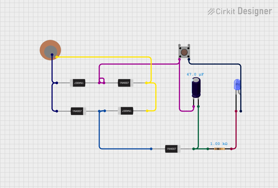
Piezo Sensor-Based LED Indicator with Pushbutton Control
Image of project: A project utilizing 1N5817 Schottky Diode (300 mil) in a practical application
This circuit is a rectifier and indicator system that uses multiple 1N4007 diodes to rectify an AC signal, a piezo sensor for signal detection, and a pushbutton to control the circuit. The rectified signal is filtered by an electrolytic capacitor and a resistor, and the presence of the signal is indicated by a blue LED.
Cirkit Designer LogoOpen Project in Cirkit Designer
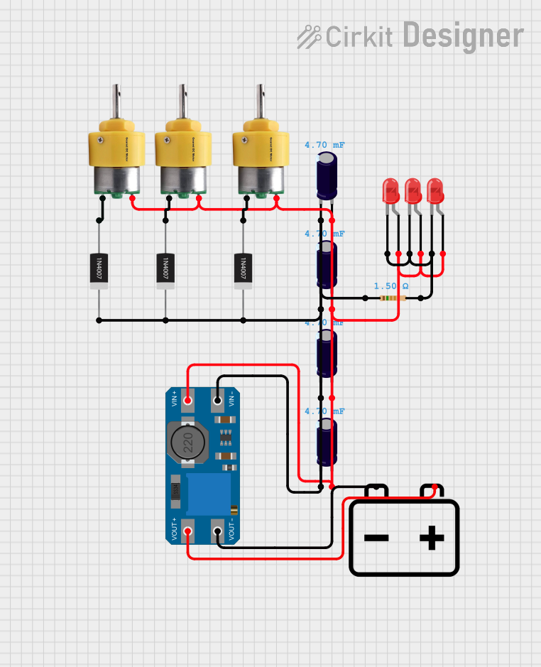
Battery-Powered Motor Control Circuit with LED Indicators
Image of footpath electricity generator: A project utilizing 1N5817 Schottky Diode (300 mil) in a practical application
This circuit consists of three Center Shaft Metal Geared Motors, each protected by a 1N4007 Rectifier Diode, and powered by a 12V battery through an MT3608 boost converter. The circuit also includes multiple electrolytic capacitors for filtering and three red LEDs with a current-limiting resistor, indicating the operational status of the motors.
Cirkit Designer LogoOpen Project in Cirkit Designer
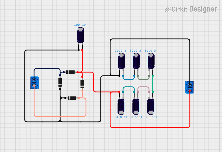
Diode and Capacitor-Based Voltage Regulation Circuit
Image of Pavetra#2: A project utilizing 1N5817 Schottky Diode (300 mil) in a practical application
This circuit is a complex network of diodes and electrolytic capacitors connected to two terminal PCB 2-pin connectors. The diodes are arranged in a series-parallel configuration, while the capacitors are connected in a manner that suggests filtering or energy storage purposes. The overall design appears to be aimed at rectification and smoothing of an input signal.
Cirkit Designer LogoOpen Project in Cirkit Designer

Explore Projects Built with 1N5817 Schottky Diode (300 mil)

Use Cirkit Designer to design, explore, and prototype these projects online. Some projects support real-time simulation. Click "Open Project" to start designing instantly!
Image of stm32 braile: A project utilizing 1N5817 Schottky Diode (300 mil) in a practical application
STM32 Nucleo-Controlled Solenoid Actuation System
This circuit appears to be a microcontroller-driven array of push-pull solenoids with flyback diodes for protection. The STM32 Nucleo F303RE microcontroller's GPIO pins are connected to the gates of several nMOS transistors, which act as switches to control the current flow to the solenoids. A pushbutton with a pull-up resistor is also interfaced with the microcontroller for user input, and the power supply is connected to the solenoids with ground return paths through the nMOS transistors.
Cirkit Designer LogoOpen Project in Cirkit Designer
Image of project: A project utilizing 1N5817 Schottky Diode (300 mil) in a practical application
Piezo Sensor-Based LED Indicator with Pushbutton Control
This circuit is a rectifier and indicator system that uses multiple 1N4007 diodes to rectify an AC signal, a piezo sensor for signal detection, and a pushbutton to control the circuit. The rectified signal is filtered by an electrolytic capacitor and a resistor, and the presence of the signal is indicated by a blue LED.
Cirkit Designer LogoOpen Project in Cirkit Designer
Image of footpath electricity generator: A project utilizing 1N5817 Schottky Diode (300 mil) in a practical application
Battery-Powered Motor Control Circuit with LED Indicators
This circuit consists of three Center Shaft Metal Geared Motors, each protected by a 1N4007 Rectifier Diode, and powered by a 12V battery through an MT3608 boost converter. The circuit also includes multiple electrolytic capacitors for filtering and three red LEDs with a current-limiting resistor, indicating the operational status of the motors.
Cirkit Designer LogoOpen Project in Cirkit Designer
Image of Pavetra#2: A project utilizing 1N5817 Schottky Diode (300 mil) in a practical application
Diode and Capacitor-Based Voltage Regulation Circuit
This circuit is a complex network of diodes and electrolytic capacitors connected to two terminal PCB 2-pin connectors. The diodes are arranged in a series-parallel configuration, while the capacitors are connected in a manner that suggests filtering or energy storage purposes. The overall design appears to be aimed at rectification and smoothing of an input signal.
Cirkit Designer LogoOpen Project in Cirkit Designer

Common Applications

  • Power supply rectification
  • Reverse polarity protection
  • Voltage clamping
  • DC-DC converters
  • Solar panel systems
  • Battery charging circuits

Technical Specifications

The 1N5817 Schottky diode is characterized by its low forward voltage drop and high current handling capability. Below are the key technical details:

Parameter Value
Maximum Repetitive Peak Reverse Voltage (VRRM) 20 V
Maximum Average Forward Rectified Current (IF(AV)) 1 A
Peak Forward Surge Current (IFSM) 25 A (8.3 ms single half-sine wave)
Forward Voltage Drop (VF) 0.45 V (at 1 A)
Reverse Current (IR) 1 mA (at 20 V, 25°C)
Operating Temperature Range -65°C to +125°C
Package Type DO-41 (300 mil)

Pin Configuration

The 1N5817 is a two-terminal device with the following pin configuration:

Pin Name Description
1 Anode Positive terminal of the diode
2 Cathode Negative terminal of the diode

The cathode is typically marked with a silver or white band on the diode body.

Usage Instructions

How to Use the 1N5817 in a Circuit

  1. Identify the Anode and Cathode: The cathode is marked with a silver or white band. Connect the anode to the positive side of the circuit and the cathode to the negative side.
  2. Insert in the Correct Orientation: Ensure the diode is oriented correctly to allow current flow in the desired direction and block reverse current.
  3. Use in Rectification: For rectification, connect the diode in series with the AC source to convert it to DC.
  4. Reverse Polarity Protection: Place the diode in series with the power supply input to prevent damage from reverse polarity.
  5. Heat Dissipation: If operating near the maximum current rating, consider adding a heatsink or ensuring adequate ventilation to prevent overheating.

Important Considerations

  • Voltage Rating: Ensure the reverse voltage does not exceed 20 V to avoid breakdown.
  • Current Rating: Do not exceed the maximum average forward current of 1 A to prevent damage.
  • Forward Voltage Drop: Account for the 0.45 V drop when designing low-voltage circuits.
  • Temperature: Operate within the specified temperature range for reliable performance.

Example: Using the 1N5817 with an Arduino UNO

The 1N5817 can be used to protect an Arduino UNO from reverse polarity. Below is an example circuit and code:

Circuit Description

  • Connect the anode of the 1N5817 to the positive terminal of the power supply.
  • Connect the cathode to the VIN pin of the Arduino UNO.
  • The diode will block reverse current if the power supply is connected incorrectly.

Arduino Code Example

// Example: Simple LED Blink with Reverse Polarity Protection
// This code assumes the 1N5817 is protecting the Arduino's VIN pin.

int ledPin = 13; // Built-in LED pin on Arduino UNO

void setup() {
  pinMode(ledPin, OUTPUT); // Set LED pin as output
}

void loop() {
  digitalWrite(ledPin, HIGH); // Turn the LED on
  delay(1000);               // Wait for 1 second
  digitalWrite(ledPin, LOW);  // Turn the LED off
  delay(1000);               // Wait for 1 second
}

Troubleshooting and FAQs

Common Issues

  1. Diode Overheating:

    • Cause: Exceeding the maximum current rating or insufficient heat dissipation.
    • Solution: Reduce the current load or add a heatsink.
  2. No Current Flow:

    • Cause: Incorrect orientation of the diode.
    • Solution: Verify the anode and cathode connections.
  3. High Reverse Leakage Current:

    • Cause: Operating at high temperatures or exceeding the reverse voltage rating.
    • Solution: Ensure the reverse voltage is within the specified limit and improve cooling.
  4. Circuit Not Working as Expected:

    • Cause: Forward voltage drop not accounted for in low-voltage circuits.
    • Solution: Adjust the circuit design to compensate for the 0.45 V drop.

FAQs

Q: Can I use the 1N5817 for AC rectification?
A: Yes, the 1N5817 is suitable for low-voltage AC rectification. However, ensure the peak reverse voltage of the AC signal does not exceed 20 V.

Q: What happens if I exceed the maximum current rating?
A: Exceeding the 1 A current rating can cause the diode to overheat and fail. Use a diode with a higher current rating if needed.

Q: How do I identify the cathode on the diode?
A: The cathode is marked with a silver or white band on the diode body.

Q: Can I use the 1N5817 in high-frequency circuits?
A: Yes, the 1N5817's fast switching speed makes it suitable for high-frequency applications like DC-DC converters.

By following this documentation, you can effectively integrate the 1N5817 Schottky diode into your electronic projects.