How to Use JST SH1 x3 Female: Examples, Pinouts, and Specs
Introduction
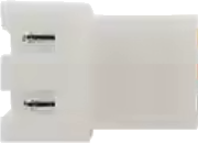
The JST SH1 x3 Female is a compact and reliable connector designed for use in electronic circuits. It features three female terminals, making it ideal for applications requiring secure and space-efficient wire connections. This connector is widely used in robotics, drones, IoT devices, and other compact electronic systems where size and reliability are critical.
Explore Projects Built with JST SH1 x3 Female


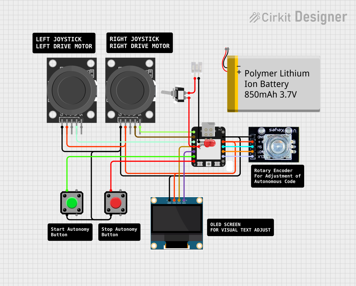
Explore Projects Built with JST SH1 x3 Female
Common Applications and Use Cases
- Connecting sensors, actuators, or modules in compact electronic devices
- Power and signal transmission in drones and robotics
- Interfacing with small PCBs or breakout boards
- Use in wearable electronics and IoT devices
Technical Specifications
The following table outlines the key technical details of the JST SH1 x3 Female connector:
| Parameter | Specification |
|---|---|
| Connector Type | JST SH1 |
| Number of Terminals | 3 (Female) |
| Pitch (Terminal Spacing) | 1.0 mm |
| Current Rating | 1.0 A (maximum) |
| Voltage Rating | 50 V (maximum) |
| Wire Gauge Supported | 32 AWG to 28 AWG |
| Operating Temperature | -25°C to +85°C |
| Material | Housing: Nylon, Contacts: Phosphor Bronze |
Pin Configuration and Descriptions
The JST SH1 x3 Female connector has three terminals, typically used for power, ground, and signal connections. The pinout is as follows:
| Pin Number | Label | Description |
|---|---|---|
| 1 | VCC | Power supply (positive voltage) |
| 2 | GND | Ground (0V reference) |
| 3 | Signal | Data or control signal |
Usage Instructions
How to Use the JST SH1 x3 Female in a Circuit
- Wire Preparation: Strip the insulation from the wires to expose approximately 1-2 mm of the conductor. Ensure the wire gauge is within the supported range (32 AWG to 28 AWG).
- Crimping: Use a compatible crimping tool to attach the crimp terminals to the wires. Ensure a secure and reliable connection.
- Insertion: Insert the crimped terminals into the connector housing until they click into place.
- Mating: Connect the JST SH1 x3 Female to its corresponding male connector. Ensure proper alignment to avoid damage.
Important Considerations and Best Practices
- Wire Gauge: Use wires within the specified gauge range to ensure proper crimping and electrical performance.
- Current and Voltage Limits: Do not exceed the maximum current (1.0 A) or voltage (50 V) ratings to prevent overheating or damage.
- Secure Connections: Double-check that the terminals are fully inserted into the housing and that the connector is properly mated.
- Environmental Conditions: Avoid exposing the connector to temperatures or environments outside its operating range (-25°C to +85°C).
Example: Connecting to an Arduino UNO
The JST SH1 x3 Female can be used to connect a sensor to an Arduino UNO. Below is an example of wiring and code for reading data from a sensor:
Wiring
- Pin 1 (VCC): Connect to the Arduino's 5V pin.
- Pin 2 (GND): Connect to the Arduino's GND pin.
- Pin 3 (Signal): Connect to an analog input pin (e.g., A0) on the Arduino.
Code Example
// Example code for reading an analog sensor connected via JST SH1 x3 Female
const int sensorPin = A0; // Signal pin connected to Arduino analog pin A0
int sensorValue = 0;      // Variable to store the sensor reading

void setup() {
  Serial.begin(9600); // Initialize serial communication at 9600 baud
}

void loop() {
  sensorValue = analogRead(sensorPin); // Read the sensor value
  Serial.print("Sensor Value: ");      // Print the sensor value to the serial monitor
  Serial.println(sensorValue);
  delay(500); // Wait for 500 milliseconds before the next reading
}
Troubleshooting and FAQs
Common Issues and Solutions
Loose Connections:
- Issue: The connector feels loose or the circuit is intermittent.
- Solution: Ensure the crimp terminals are securely attached to the wires and fully inserted into the housing.
Incorrect Pinout:
- Issue: The circuit does not work as expected.
- Solution: Double-check the pinout and ensure the connections match the intended design.
Overheating:
- Issue: The connector or wires become hot during operation.
- Solution: Verify that the current and voltage do not exceed the specified ratings.
Damaged Terminals:
- Issue: The terminals are bent or do not make proper contact.
- Solution: Replace the damaged terminals and ensure proper crimping.
FAQs
Q: Can I use this connector for high-power applications?
- A: No, the JST SH1 x3 Female is designed for low-power applications with a maximum current rating of 1.0 A.
Q: What crimping tool should I use?
- A: Use a crimping tool compatible with JST SH1 terminals to ensure proper crimping.
Q: Can I solder wires directly to the connector?
- A: While possible, soldering is not recommended as it may damage the housing or reduce reliability.
Q: Is this connector compatible with other JST series?
- A: No, the JST SH1 x3 Female is specifically designed for the SH1 series and may not be compatible with other JST series due to differences in pitch and design.