Cirkit Designer
Your all-in-one circuit design IDE
Home /
Component Documentation
How to Use spdt: Examples, Pinouts, and Specs
Introduction
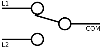
- A Single Pole Double Throw (SPDT) switch is an electrical switch that allows a single input to connect to one of two outputs. It is commonly used to control circuits from multiple locations or to toggle between two different circuit paths.
- SPDT switches are widely used in applications such as lighting control, motor direction control, audio signal routing, and power supply selection.
Explore Projects Built with spdt
Basic Surge Protection Circuit with Benedict Switch

The circuit includes a Benedict Switch connected in series with a Fuse Holder and an SPD (Surge Protection Device). The SPD is also connected to a Ground reference. This configuration suggests that the circuit is designed to control power flow, protect against overcurrent with the fuse, and guard against voltage surges with the SPD, with a safe path to ground for surge dissipation.
ESP32-Based Solar-Powered Environmental Monitoring System
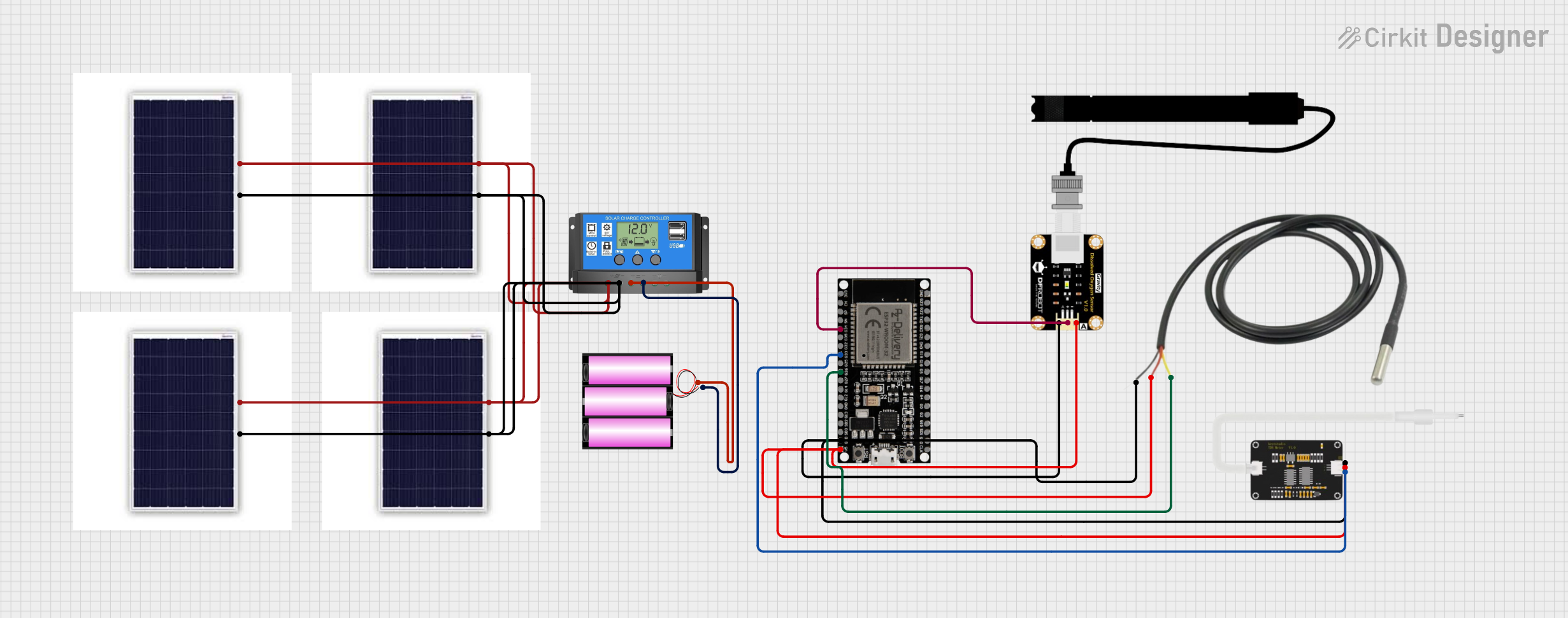
This circuit is a solar-powered environmental monitoring system. It uses an ESP32 microcontroller to collect data from a TDS sensor, a dissolved oxygen sensor, and a temperature sensor. The system is powered by a 12V battery charged through a solar charge controller connected to multiple solar panels.
ESP32-Based Environmental Monitoring System with Wi-Fi Connectivity
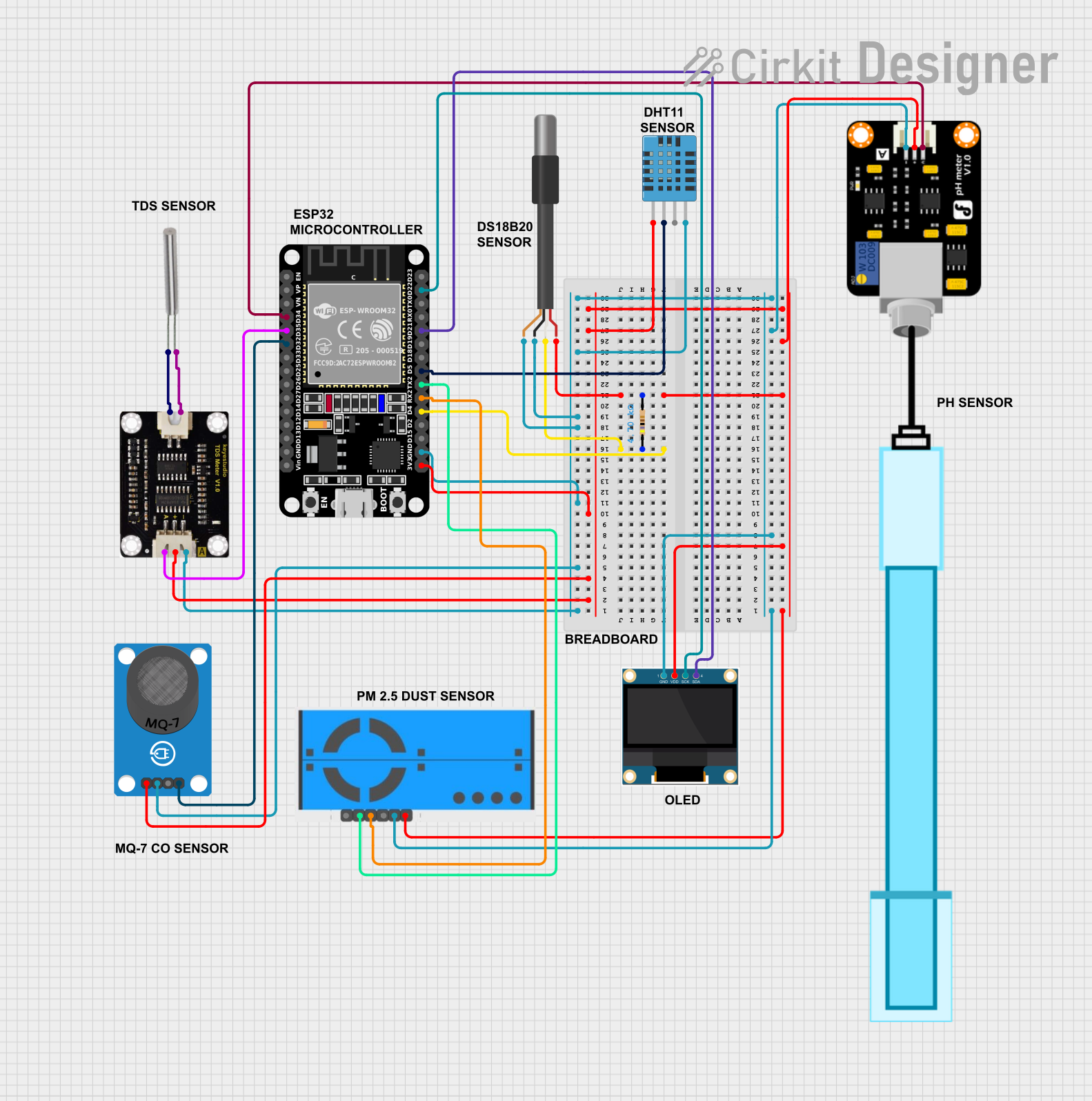
This circuit is an environmental monitoring system using an ESP32 microcontroller to collect data from various sensors, including temperature, humidity, air quality, pH, and TDS sensors. The collected data is displayed on an OLED screen, sent to ThingSpeak for remote monitoring, and email alerts are sent if critical thresholds are exceeded.
ESP32-Based Water Quality Monitoring System with Solar Charging
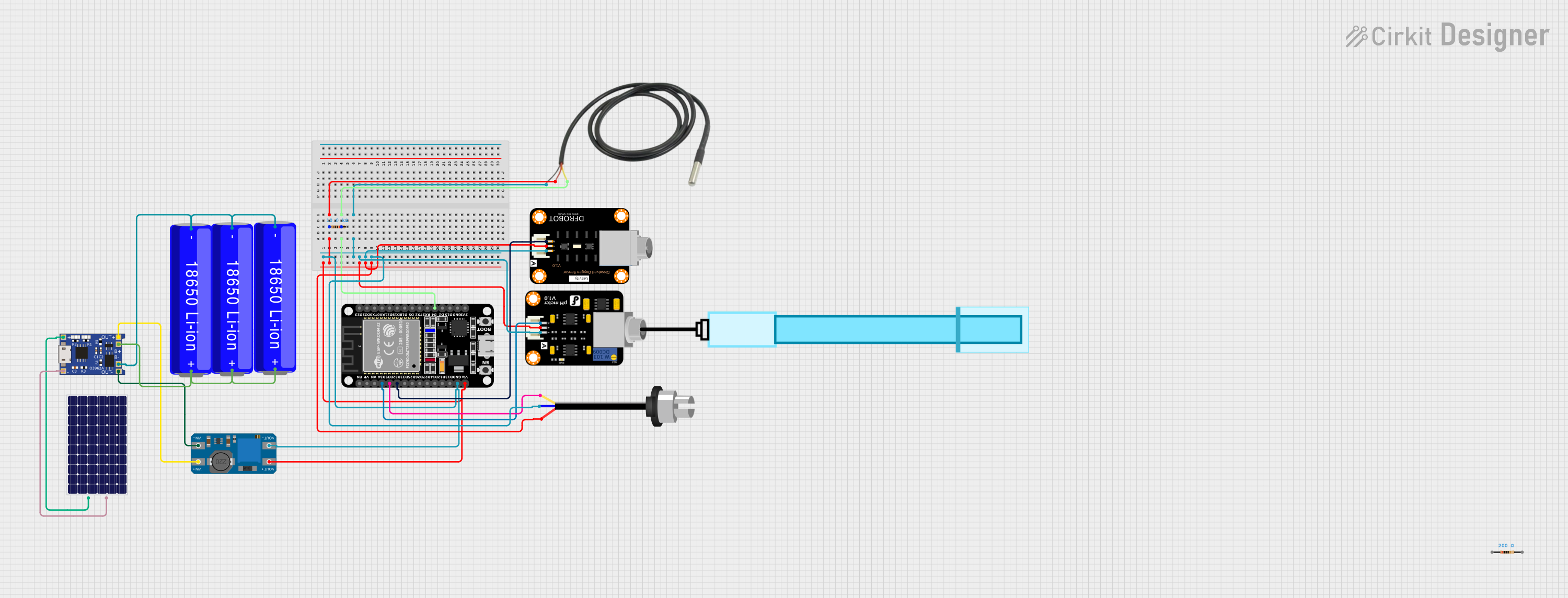
This circuit features an ESP32 microcontroller interfaced with various sensors including a temperature sensor, a pH meter, a dissolved oxygen sensor, and a turbidity sensor for environmental monitoring. Power management is handled by a TP4056 charging module connected to a solar panel and three 18650 Li-ion batteries in parallel, with a MT3608 boost converter to step up the voltage for the ESP32 and sensors. The ESP32 reads sensor data and likely transmits it for analysis or remote monitoring, although the specific functionality would be determined by the microcontroller's code, which is not provided.
Explore Projects Built with spdt
Basic Surge Protection Circuit with Benedict Switch
The circuit includes a Benedict Switch connected in series with a Fuse Holder and an SPD (Surge Protection Device). The SPD is also connected to a Ground reference. This configuration suggests that the circuit is designed to control power flow, protect against overcurrent with the fuse, and guard against voltage surges with the SPD, with a safe path to ground for surge dissipation.
ESP32-Based Solar-Powered Environmental Monitoring System
This circuit is a solar-powered environmental monitoring system. It uses an ESP32 microcontroller to collect data from a TDS sensor, a dissolved oxygen sensor, and a temperature sensor. The system is powered by a 12V battery charged through a solar charge controller connected to multiple solar panels.
ESP32-Based Environmental Monitoring System with Wi-Fi Connectivity
This circuit is an environmental monitoring system using an ESP32 microcontroller to collect data from various sensors, including temperature, humidity, air quality, pH, and TDS sensors. The collected data is displayed on an OLED screen, sent to ThingSpeak for remote monitoring, and email alerts are sent if critical thresholds are exceeded.
ESP32-Based Water Quality Monitoring System with Solar Charging
This circuit features an ESP32 microcontroller interfaced with various sensors including a temperature sensor, a pH meter, a dissolved oxygen sensor, and a turbidity sensor for environmental monitoring. Power management is handled by a TP4056 charging module connected to a solar panel and three 18650 Li-ion batteries in parallel, with a MT3608 boost converter to step up the voltage for the ESP32 and sensors. The ESP32 reads sensor data and likely transmits it for analysis or remote monitoring, although the specific functionality would be determined by the microcontroller's code, which is not provided.
Technical Specifications
- Type: Single Pole Double Throw (SPDT)
- Switching Mechanism: Mechanical or electronic
- Voltage Rating: Typically ranges from 5V to 250V (depending on the model)
- Current Rating: Typically ranges from 0.5A to 15A (depending on the model)
- Contact Resistance: < 50 mΩ (typical)
- Insulation Resistance: > 100 MΩ at 500V DC
- Operating Temperature: -40°C to +85°C (varies by model)
- Lifespan: Mechanical lifespan of 10,000 to 1,000,000 cycles (varies by model)
Pin Configuration and Descriptions
The SPDT switch typically has three terminals:
| Pin Name | Description |
|---|---|
| Common (C) | The input terminal that connects to one of the two output terminals. |
| Normally Open (NO) | The terminal that connects to the common terminal when the switch is activated. |
| Normally Closed (NC) | The terminal that connects to the common terminal when the switch is not activated. |
Usage Instructions
How to Use the SPDT Switch in a Circuit
- Identify the Terminals: Locate the Common (C), Normally Open (NO), and Normally Closed (NC) terminals on the switch.
- Connect the Input: Connect the input signal or power source to the Common (C) terminal.
- Connect the Outputs:
- Connect one output device or circuit to the Normally Open (NO) terminal.
- Connect the other output device or circuit to the Normally Closed (NC) terminal.
- Control the Switch: Toggle the switch to route the input signal to either the NO or NC terminal, depending on the desired output.
Important Considerations and Best Practices
- Voltage and Current Ratings: Ensure the switch's voltage and current ratings are suitable for your application to avoid damage or failure.
- Debouncing: For mechanical SPDT switches, consider using a debouncing circuit or software to eliminate noise caused by rapid on/off switching.
- Mounting: Securely mount the switch to prevent accidental disconnections or damage.
- Polarity: SPDT switches are generally non-polarized, but verify the connections in your specific application.
Example: Using an SPDT Switch with an Arduino UNO
An SPDT switch can be used to toggle between two LEDs using an Arduino UNO. Below is an example circuit and code:
Circuit Connections
- Connect the Common (C) terminal of the SPDT switch to pin 2 of the Arduino.
- Connect the Normally Open (NO) terminal to one LED (with a 220Ω resistor in series) and then to ground.
- Connect the Normally Closed (NC) terminal to another LED (with a 220Ω resistor in series) and then to ground.
Arduino Code
// Define the pin connected to the SPDT switch
const int switchPin = 2;

// Define the pins connected to the LEDs
const int led1 = 3; // LED connected to Normally Open (NO)
const int led2 = 4; // LED connected to Normally Closed (NC)

void setup() {
  pinMode(switchPin, INPUT_PULLUP); // Set switch pin as input with pull-up resistor
  pinMode(led1, OUTPUT);            // Set LED1 pin as output
  pinMode(led2, OUTPUT);            // Set LED2 pin as output
}

void loop() {
  int switchState = digitalRead(switchPin); // Read the state of the switch

  if (switchState == LOW) {
    // If the switch is toggled to NO, turn on LED1 and turn off LED2
    digitalWrite(led1, HIGH);
    digitalWrite(led2, LOW);
  } else {
    // If the switch is toggled to NC, turn on LED2 and turn off LED1
    digitalWrite(led1, LOW);
    digitalWrite(led2, HIGH);
  }
}
Troubleshooting and FAQs
Common Issues
- Switch Not Working:
- Ensure the connections are correct and secure.
- Verify that the switch is rated for the voltage and current in your circuit.
- Intermittent Behavior:
- Mechanical switches may produce noise or bouncing. Use a debouncing circuit or software to address this issue.
- LEDs Not Lighting Up in Arduino Circuit:
- Check the wiring and ensure the resistors are properly connected.
- Verify that the Arduino pin modes and logic levels are correctly configured in the code.
FAQs
Q: Can I use an SPDT switch to control AC devices?
A: Yes, as long as the switch is rated for the AC voltage and current of your application.
Q: What is the difference between SPDT and DPDT switches?
A: An SPDT switch has one input and two outputs, while a DPDT (Double Pole Double Throw) switch has two inputs and four outputs, allowing for more complex switching configurations.
Q: How do I debounce an SPDT switch?
A: You can use a capacitor and resistor in a hardware debouncing circuit or implement a software debounce routine in your microcontroller code.