How to Use ILI9341: Examples, Pinouts, and Specs
Introduction
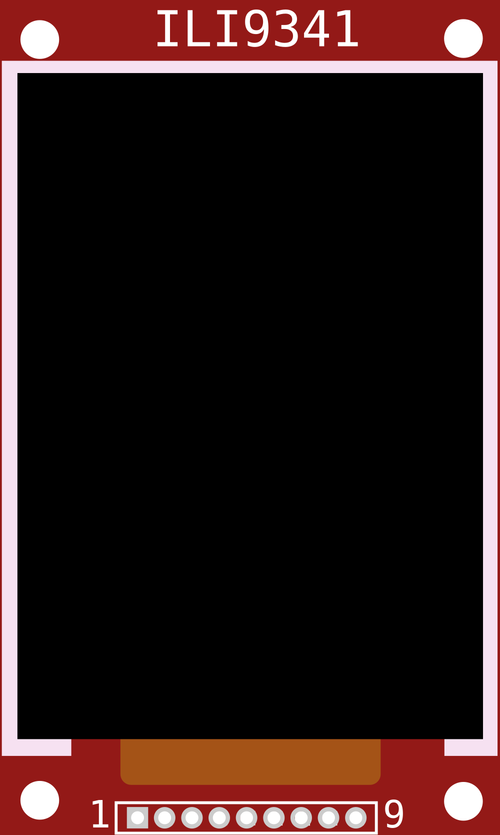
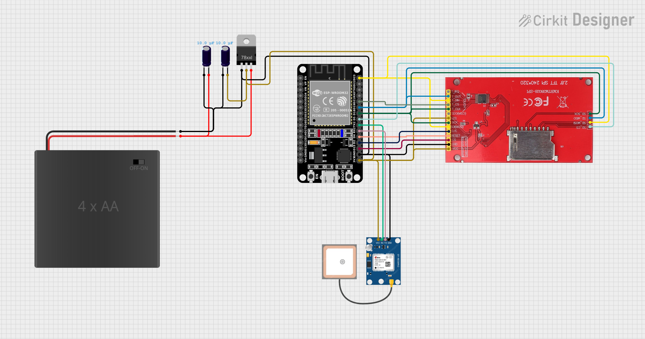
The ILI9341 is a widely-used TFT LCD controller that powers various display modules. It supports a resolution of 240x320 pixels and can interface with microcontrollers through SPI or parallel communication. This versatility makes it a popular choice for embedded systems requiring graphical displays, such as handheld devices, instrumentation panels, and user interfaces for various electronic projects.
Explore Projects Built with ILI9341
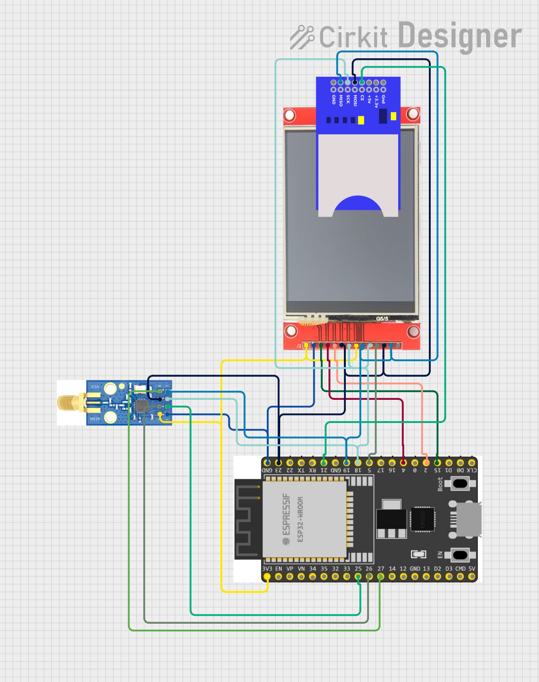
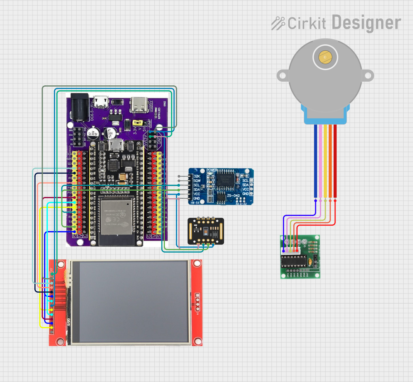
Explore Projects Built with ILI9341
Technical Specifications
Key Technical Details
| Parameter | Value |
|---|---|
| Resolution | 240x320 pixels |
| Interface | SPI, Parallel |
| Operating Voltage | 2.8V - 3.3V |
| Current Consumption | 2mA (typical) |
| Display Colors | 262K / 65K |
| Viewing Angle | 80°/80°/80°/80° (L/R/U/D) |
| Operating Temperature | -20°C to 70°C |
Pin Configuration and Descriptions
SPI Interface
| Pin No. | Pin Name | Description |
|---|---|---|
| 1 | VCC | Power Supply (2.8V - 3.3V) |
| 2 | GND | Ground |
| 3 | CS | Chip Select |
| 4 | RESET | Reset |
| 5 | DC/RS | Data/Command Select |
| 6 | SDI/MOSI | Serial Data Input / Master Out Slave In |
| 7 | SCK | Serial Clock |
| 8 | LED | Backlight Control |
| 9 | SDO/MISO | Serial Data Output / Master In Slave Out (optional) |
Parallel Interface
| Pin No. | Pin Name | Description |
|---|---|---|
| 1 | VCC | Power Supply (2.8V - 3.3V) |
| 2 | GND | Ground |
| 3 | CS | Chip Select |
| 4 | RESET | Reset |
| 5 | DC/RS | Data/Command Select |
| 6-13 | D0-D7 | Data Bus |
| 14 | WR | Write Strobe |
| 15 | RD | Read Strobe |
| 16 | LED | Backlight Control |
Usage Instructions
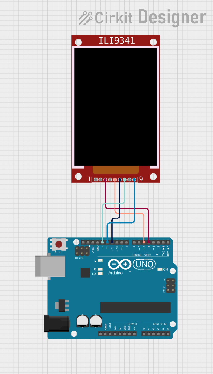
Connecting to an Arduino UNO (SPI Interface)
Wiring:
- VCC to 3.3V
- GND to GND
- CS to Digital Pin 10
- RESET to Digital Pin 9
- DC/RS to Digital Pin 8
- SDI/MOSI to Digital Pin 11
- SCK to Digital Pin 13
- LED to 3.3V (through a current-limiting resistor if necessary)
Library Installation:
- Install the Adafruit ILI9341 library from the Arduino Library Manager.
Sample Code:
#include <Adafruit_GFX.h>    // Core graphics library
#include <Adafruit_ILI9341.h> // Hardware-specific library

// Pin definitions
#define TFT_CS     10
#define TFT_RST    9
#define TFT_DC     8

// Create an instance of the display
Adafruit_ILI9341 tft = Adafruit_ILI9341(TFT_CS, TFT_DC, TFT_RST);

void setup() {
  tft.begin(); // Initialize the display
  tft.setRotation(1); // Set display orientation
  tft.fillScreen(ILI9341_BLACK); // Clear the screen
  tft.setTextColor(ILI9341_WHITE); // Set text color
  tft.setTextSize(2); // Set text size
  tft.setCursor(10, 10); // Set cursor position
  tft.print("Hello, World!"); // Print text
}

void loop() {
  // Your code here
}
Important Considerations and Best Practices
- Power Supply: Ensure the ILI9341 is powered with a stable 3.3V supply. Using 5V can damage the display.
- Level Shifting: If your microcontroller operates at 5V logic levels, use level shifters to interface with the ILI9341.
- Backlight Control: Use a current-limiting resistor for the LED pin to prevent excessive current draw.
- Initialization: Always initialize the display in your setup code to ensure proper operation.
Troubleshooting and FAQs
Common Issues
Blank Screen:
- Solution: Check all connections, ensure the power supply is stable, and verify the initialization code.
Garbled Display:
- Solution: Ensure correct wiring, especially for the SPI pins. Verify that the correct pins are defined in the code.
Flickering Display:
- Solution: Check the power supply for noise or instability. Use decoupling capacitors if necessary.
FAQs
Q: Can I use the ILI9341 with a 5V microcontroller? A: Yes, but you must use level shifters to convert 5V logic levels to 3.3V.
Q: How do I control the backlight? A: Connect the LED pin to 3.3V through a current-limiting resistor. You can also use a PWM pin on your microcontroller for dimming.
Q: Can I use the ILI9341 in parallel mode with an Arduino UNO? A: The Arduino UNO has limited pins, making parallel mode impractical. SPI mode is recommended for the UNO.
By following this documentation, you should be able to successfully integrate the ILI9341 TFT LCD controller into your projects, whether you are a beginner or an experienced user.