How to Use Top LM7805 PCB Board: Examples, Pinouts, and Specs
Introduction
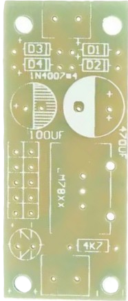
The Top LM7805 PCB Board is a compact and efficient printed circuit board designed to house the LM7805 voltage regulator. This board simplifies the process of creating a stable 5V DC power supply from a higher voltage input, such as 9V, 12V, or 15V. It is ideal for powering microcontrollers, sensors, and other low-voltage electronic components in a variety of applications.
Explore Projects Built with Top LM7805 PCB Board


Explore Projects Built with Top LM7805 PCB Board
Common Applications and Use Cases
- Powering Arduino boards, Raspberry Pi, and other microcontrollers
- Supplying stable 5V power to sensors and modules
- DIY electronics projects requiring regulated 5V output
- Prototyping and testing circuits with a reliable power source
Technical Specifications
The Top LM7805 PCB Board is designed to work seamlessly with the LM7805 voltage regulator and includes supporting components for optimal performance.
Key Technical Details
- Input Voltage Range: 7V to 25V DC
- Output Voltage: 5V DC (regulated)
- Maximum Output Current: 1A (with proper heat dissipation)
- PCB Dimensions: Typically 25mm x 30mm (may vary slightly)
- Onboard Components:
- Input and output capacitors for voltage stability
- Screw terminals for easy input/output connections
- Heat sink mounting area for the LM7805 regulator
Pin Configuration and Descriptions
The LM7805 regulator on the PCB has three pins, which are connected to the following terminals:
| Pin Number | Pin Name | Description |
|---|---|---|
| 1 | Input (VIN) | Connects to the unregulated DC input voltage. |
| 2 | Ground (GND) | Common ground for input and output. |
| 3 | Output (VOUT) | Provides the regulated 5V DC output. |
The PCB also includes screw terminals for easy wiring:
| Terminal Name | Description |
|---|---|
| VIN | Connects to the unregulated DC input voltage. |
| GND | Common ground for input and output. |
| VOUT | Provides the regulated 5V DC output. |
Usage Instructions
How to Use the Top LM7805 PCB Board in a Circuit
Connect the Input Voltage:
- Attach the positive terminal of your DC power source (7V to 25V) to the
VINterminal. - Connect the negative terminal of your power source to the
GNDterminal.
- Attach the positive terminal of your DC power source (7V to 25V) to the
Connect the Output Load:
- Connect the positive terminal of your load (e.g., microcontroller, sensor) to the
VOUTterminal. - Connect the ground of your load to the
GNDterminal.
- Connect the positive terminal of your load (e.g., microcontroller, sensor) to the
Optional Heat Sink:
- If your load requires high current (close to 1A), attach a heat sink to the LM7805 regulator to prevent overheating.
Power On:
- Turn on your DC power source. The PCB will regulate the input voltage and provide a stable 5V output.
Important Considerations and Best Practices
- Ensure the input voltage is at least 2V higher than the desired 5V output (minimum 7V input).
- Use a heat sink if the regulator gets too hot during operation.
- Avoid exceeding the maximum input voltage (25V) or output current (1A) to prevent damage.
- Verify all connections before powering on the circuit to avoid short circuits or incorrect wiring.
Example: Using the Top LM7805 PCB Board with an Arduino UNO
The Top LM7805 PCB Board can be used to power an Arduino UNO by providing a stable 5V supply. Below is an example of how to connect the board:
- Connect a 9V battery to the
VINandGNDterminals of the PCB. - Connect the
VOUTterminal of the PCB to the 5V pin of the Arduino UNO. - Connect the
GNDterminal of the PCB to the GND pin of the Arduino UNO.
Here is a simple Arduino code example to test the setup:
// Simple LED Blink Example
// This code blinks an LED connected to pin 13 of the Arduino UNO.
// Ensure the Arduino is powered via the Top LM7805 PCB Board.

void setup() {
  pinMode(13, OUTPUT); // Set pin 13 as an output pin
}

void loop() {
  digitalWrite(13, HIGH); // Turn the LED on
  delay(1000);            // Wait for 1 second
  digitalWrite(13, LOW);  // Turn the LED off
  delay(1000);            // Wait for 1 second
}
Troubleshooting and FAQs
Common Issues and Solutions
No Output Voltage:
- Cause: Incorrect wiring or insufficient input voltage.
- Solution: Double-check the connections and ensure the input voltage is at least 7V.
Overheating Regulator:
- Cause: High current draw or insufficient heat dissipation.
- Solution: Attach a heat sink to the LM7805 regulator and reduce the load current if possible.
Fluctuating Output Voltage:
- Cause: Missing or faulty capacitors on the PCB.
- Solution: Verify that the onboard capacitors are properly soldered and functional.
Output Voltage Not 5V:
- Cause: Input voltage is too low or the regulator is damaged.
- Solution: Ensure the input voltage is at least 7V and replace the LM7805 if necessary.
FAQs
Q: Can I use the Top LM7805 PCB Board with a 6V input?
A: No, the input voltage must be at least 7V for the LM7805 to regulate properly and provide a stable 5V output.
Q: What is the maximum current the board can supply?
A: The board can supply up to 1A, but a heat sink is recommended for high current loads to prevent overheating.
Q: Can I use this board to power a 3.3V device?
A: No, the LM7805 provides a fixed 5V output. For 3.3V devices, consider using a different regulator, such as the LM1117-3.3.
Q: Is the board compatible with AC input?
A: No, the board requires a DC input voltage. Use a rectifier circuit if you need to convert AC to DC before using this board.