Cirkit Designer Logo
Cirkit Designer
Your all-in-one circuit design IDE
Home / 
Component Documentation

How to Use Adafruit Feather M0 Adalogger: Examples, Pinouts, and Specs

Image of Adafruit Feather M0 Adalogger
Cirkit Designer LogoDesign with Adafruit Feather M0 Adalogger in Cirkit Designer

Introduction

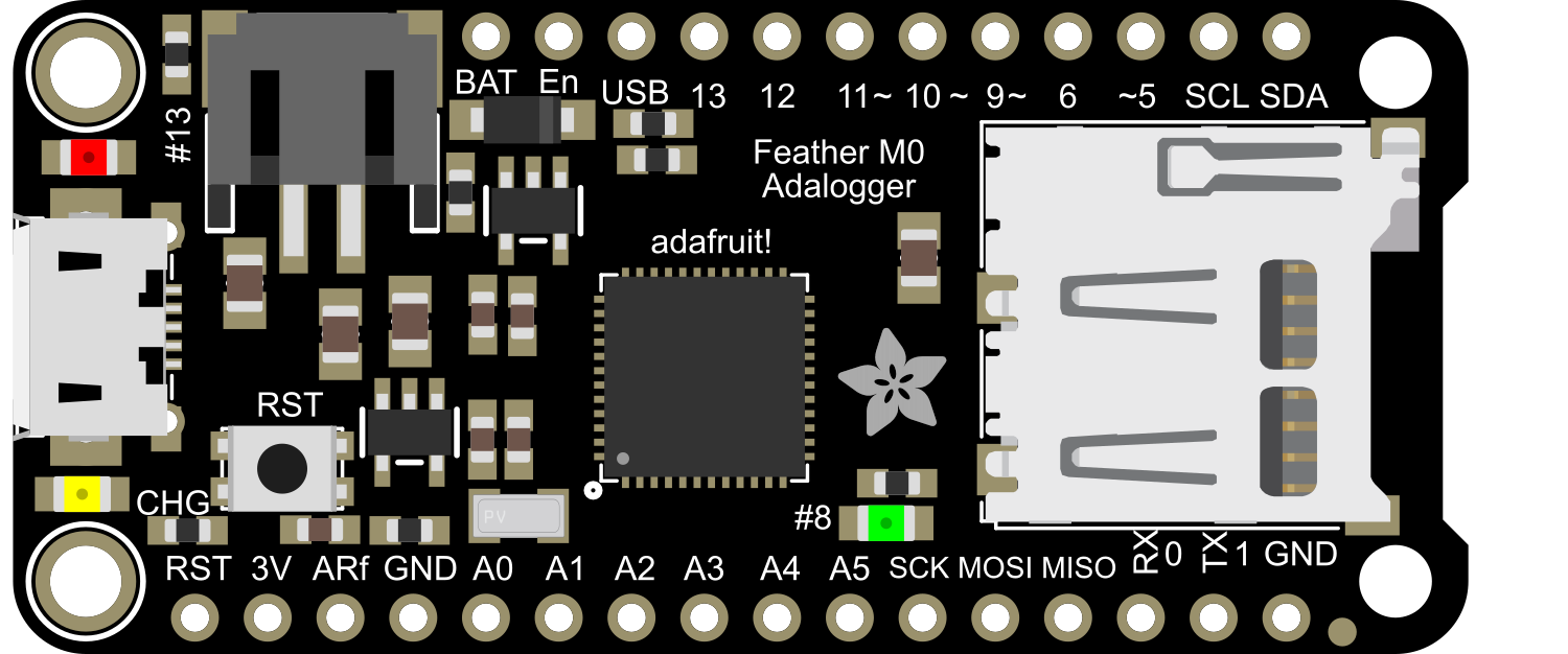
The Adafruit Feather M0 Adalogger is a versatile and portable development board that integrates the power of a microcontroller with the convenience of data logging. Based on the ATSAMD21G18 ARM Cortex M0 processor, it offers a rich set of features including an onboard microSD card slot for data storage and a real-time clock (RTC) for time-stamping data. This makes it an excellent choice for projects requiring data collection, time-sensitive operations, or portable instrumentation.

Explore Projects Built with Adafruit Feather M0 Adalogger

Use Cirkit Designer to design, explore, and prototype these projects online. Some projects support real-time simulation. Click "Open Project" to start designing instantly!
Solar-Powered Environmental Data Logger with Adafruit Feather M0 Express
Image of Lake Thoreau Monitoring Station: A project utilizing Adafruit Feather M0 Adalogger in a practical application
This circuit is designed for environmental data collection and logging, utilizing an Adafruit Feather M0 Express microcontroller as the central processing unit. It interfaces with a BME280 sensor for atmospheric temperature, humidity, and pressure measurements, an SGP30 sensor for monitoring air quality (eCO2 and TVOC), and a STEMMA soil sensor for detecting soil moisture and temperature. The system is powered by a solar panel and a 3.7v LiPo battery, managed by an Adafruit BQ24074 Solar-DC-USB Lipo Charger, and provides easy access to the microcontroller's connections through an Adafruit Terminal Breakout FeatherWing.
Cirkit Designer LogoOpen Project in Cirkit Designer
Multi-Sensor Health Monitoring System with Adafruit Feather M0 Adalogger
Image of health tracker: A project utilizing Adafruit Feather M0 Adalogger in a practical application
This circuit is designed to interface multiple sensors with an Adafruit Feather M0 Adalogger microcontroller for data logging purposes. The sensors include a MAX30205 temperature sensor, a body dehydration sensor, a MAX30102 pulse oximeter, an Adafruit LSM6DSOX 6-axis accelerometer and gyroscope, and an Adafruit BME680 environmental sensor. All sensors are connected to the microcontroller via an I2C bus, sharing the SDA and SCL lines for communication.
Cirkit Designer LogoOpen Project in Cirkit Designer
Touch-Sensitive Interface with Adafruit MPR121 and Feather 32u4 Bluefruit
Image of MPR121: A project utilizing Adafruit Feather M0 Adalogger in a practical application
This circuit integrates an Adafruit MPR121 capacitive touch sensor with an Adafruit Feather 32u4 Bluefruit microcontroller. The MPR121 is powered by the Feather and communicates via I2C (SCL and SDA) to detect touch inputs, which can be processed or transmitted wirelessly by the Feather.
Cirkit Designer LogoOpen Project in Cirkit Designer
ESP32-Based Vibration Feedback System with Quad Alphanumeric Display and ADXL343 Accelerometer
Image of EC444 - Quest 3: A project utilizing Adafruit Feather M0 Adalogger in a practical application
This circuit features an Adafruit HUZZAH32 ESP32 Feather board as the central microcontroller, which is connected to an Adafruit Quad AlphaNumeric Featherwing display and an Adafruit ADXL343 accelerometer via I2C communication (SCL and SDA lines). The ESP32 controls a vibration motor connected to one of its GPIO pins (A5_IO4) and shares a common power supply (3.3V) and ground (GND) with the other components. The purpose of this circuit is likely to read acceleration data, display information on the alphanumeric display, and provide haptic feedback through the vibration motor.
Cirkit Designer LogoOpen Project in Cirkit Designer

Explore Projects Built with Adafruit Feather M0 Adalogger

Use Cirkit Designer to design, explore, and prototype these projects online. Some projects support real-time simulation. Click "Open Project" to start designing instantly!
Image of Lake Thoreau Monitoring Station: A project utilizing Adafruit Feather M0 Adalogger in a practical application
Solar-Powered Environmental Data Logger with Adafruit Feather M0 Express
This circuit is designed for environmental data collection and logging, utilizing an Adafruit Feather M0 Express microcontroller as the central processing unit. It interfaces with a BME280 sensor for atmospheric temperature, humidity, and pressure measurements, an SGP30 sensor for monitoring air quality (eCO2 and TVOC), and a STEMMA soil sensor for detecting soil moisture and temperature. The system is powered by a solar panel and a 3.7v LiPo battery, managed by an Adafruit BQ24074 Solar-DC-USB Lipo Charger, and provides easy access to the microcontroller's connections through an Adafruit Terminal Breakout FeatherWing.
Cirkit Designer LogoOpen Project in Cirkit Designer
Image of health tracker: A project utilizing Adafruit Feather M0 Adalogger in a practical application
Multi-Sensor Health Monitoring System with Adafruit Feather M0 Adalogger
This circuit is designed to interface multiple sensors with an Adafruit Feather M0 Adalogger microcontroller for data logging purposes. The sensors include a MAX30205 temperature sensor, a body dehydration sensor, a MAX30102 pulse oximeter, an Adafruit LSM6DSOX 6-axis accelerometer and gyroscope, and an Adafruit BME680 environmental sensor. All sensors are connected to the microcontroller via an I2C bus, sharing the SDA and SCL lines for communication.
Cirkit Designer LogoOpen Project in Cirkit Designer
Image of MPR121: A project utilizing Adafruit Feather M0 Adalogger in a practical application
Touch-Sensitive Interface with Adafruit MPR121 and Feather 32u4 Bluefruit
This circuit integrates an Adafruit MPR121 capacitive touch sensor with an Adafruit Feather 32u4 Bluefruit microcontroller. The MPR121 is powered by the Feather and communicates via I2C (SCL and SDA) to detect touch inputs, which can be processed or transmitted wirelessly by the Feather.
Cirkit Designer LogoOpen Project in Cirkit Designer
Image of EC444 - Quest 3: A project utilizing Adafruit Feather M0 Adalogger in a practical application
ESP32-Based Vibration Feedback System with Quad Alphanumeric Display and ADXL343 Accelerometer
This circuit features an Adafruit HUZZAH32 ESP32 Feather board as the central microcontroller, which is connected to an Adafruit Quad AlphaNumeric Featherwing display and an Adafruit ADXL343 accelerometer via I2C communication (SCL and SDA lines). The ESP32 controls a vibration motor connected to one of its GPIO pins (A5_IO4) and shares a common power supply (3.3V) and ground (GND) with the other components. The purpose of this circuit is likely to read acceleration data, display information on the alphanumeric display, and provide haptic feedback through the vibration motor.
Cirkit Designer LogoOpen Project in Cirkit Designer

Common Applications and Use Cases

  • Environmental data logging (temperature, humidity, pressure)
  • Time-lapse photography with time-stamped data
  • Portable weather stations
  • Wearable health and fitness trackers
  • IoT devices with data backup on SD card

Technical Specifications

Key Technical Details

  • Microcontroller: ATSAMD21G18, 32-bit ARM Cortex M0+
  • Operating Voltage: 3.3V
  • Input Voltage: 3.7-6V via battery and USB, 5V via USB
  • Digital I/O Pins: 20
  • PWM Channels: 10
  • Analog Input Channels: 6 (12-bit ADC)
  • Analog Output Channels: 1 (10-bit DAC)
  • Flash Memory: 256KB
  • SRAM: 32KB
  • Clock Speed: 48 MHz
  • RTC: With backup battery support
  • MicroSD Slot: Supports standard and high capacity SD cards

Pin Configuration and Descriptions

Pin Number Function Description
1 GND Ground
2 BAT Battery positive voltage (3.7-4.2V LiPo)
3 EN Enable pin for the 3.3V regulator
4 USB USB power (5V from host computer)
5-14 Digital Pins Digital I/O, PWM output, or interrupt detection
15-20 Analog Pins Analog inputs or digital I/O
21 AREF Analog reference voltage
22 SCK SPI clock
23 MISO SPI Master In Slave Out
24 MOSI SPI Master Out Slave In
25 SDA I2C Data
26 SCL I2C Clock
27 RX UART Receive
28 TX UART Transmit
29 RST Reset pin
30 3V 3.3V output from the regulator

Usage Instructions

How to Use the Component in a Circuit

  1. Powering the Board: The Feather M0 Adalogger can be powered via USB, a LiPo battery, or an external power supply. Ensure that the power source is within the specified voltage range.

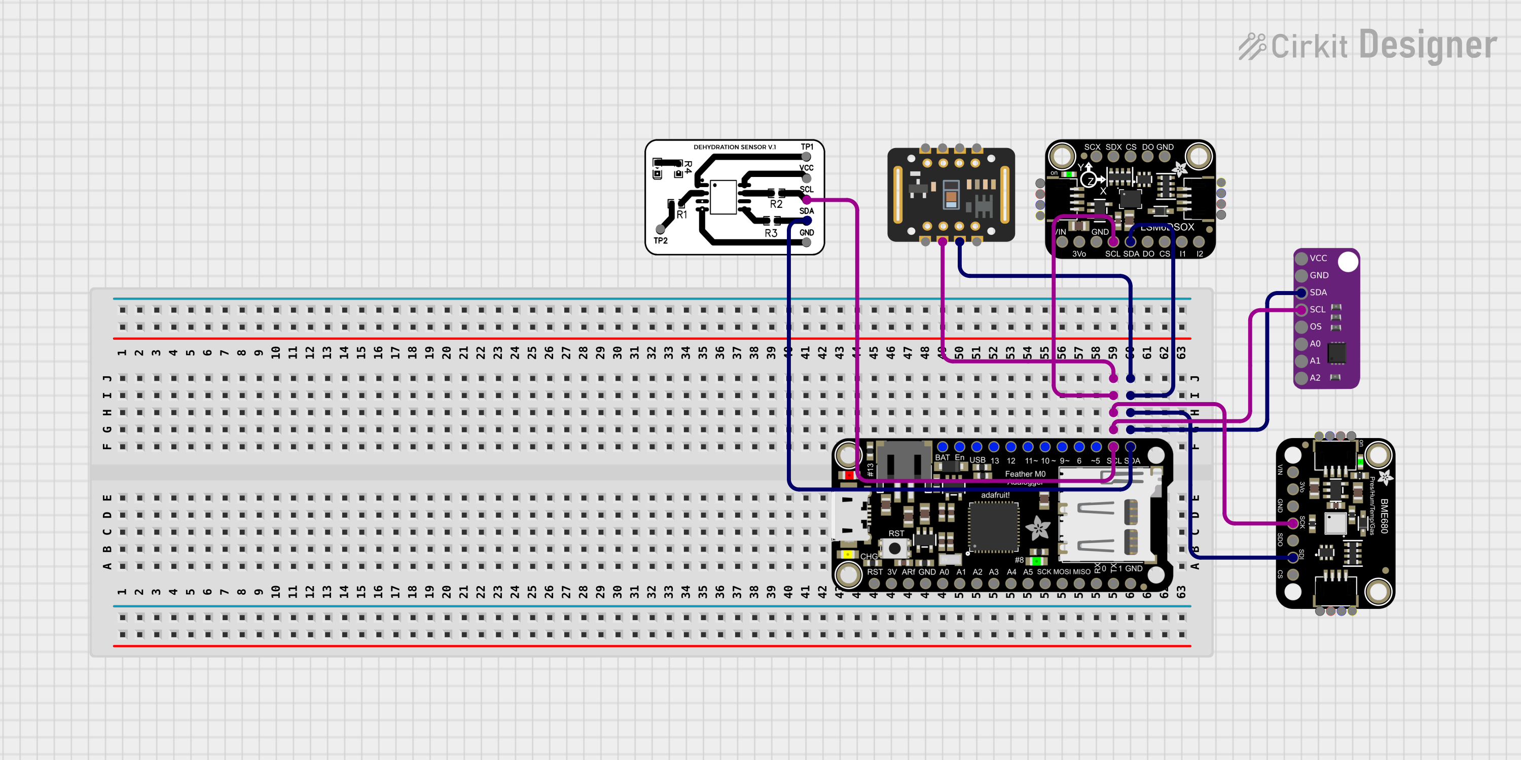
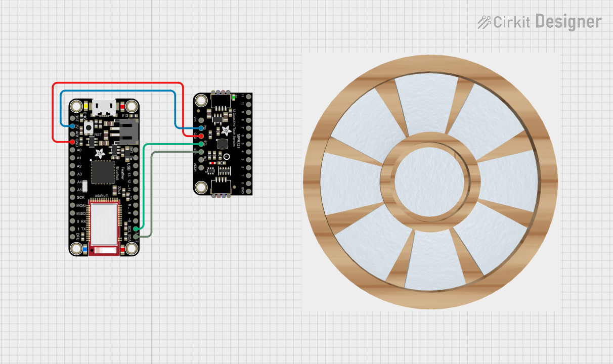
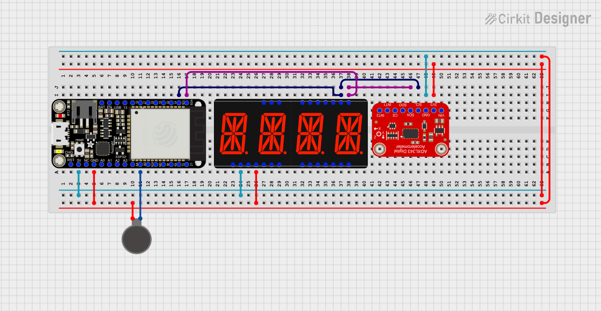
  2. Connecting Peripherals: Connect sensors and peripherals to the appropriate pins. Use digital or analog pins based on the requirements of the peripheral.

  3. Data Logging: Insert a formatted microSD card into the slot for data logging. Use the onboard RTC to timestamp your data.

  4. Programming: The board can be programmed via the Arduino IDE. Select "Adafruit Feather M0" from the board manager.

Important Considerations and Best Practices

  • Always disconnect the battery or power supply before making or altering connections.
  • Use a regulated power supply to prevent damage to the board.
  • Format the SD card as FAT16 or FAT32 before use.
  • To maintain accurate time, ensure the RTC battery is charged and properly installed.
  • Avoid exposing the board to static electricity or physical stress.

Troubleshooting and FAQs

Common Issues

  • Board not recognized by computer: Check the USB cable and connections. Ensure the correct drivers are installed.
  • SD card not working: Verify that the SD card is formatted correctly and is not corrupted.
  • Inaccurate RTC time: Check the RTC battery and replace it if necessary.

Solutions and Tips for Troubleshooting

  • If the board is not recognized, try using a different USB port or cable.
  • For SD card issues, try formatting the card on a computer or testing with a different card.
  • Ensure that the RTC battery is properly installed and making good contact.

FAQs

Q: Can I power the Feather M0 Adalogger with a 5V supply? A: Yes, you can power it through the USB connection with 5V, but do not apply 5V directly to the 3.3V pin.

Q: How do I set the time on the RTC? A: You can set the time on the RTC using the Arduino library for the RTC chip. Refer to the example code provided by Adafruit.

Q: What is the maximum size of SD card supported? A: The Feather M0 Adalogger supports SD cards up to 32GB formatted as FAT16 or FAT32.

Example Code for Arduino UNO

Below is an example code snippet for initializing the RTC and SD card on the Adafruit Feather M0 Adalogger. This code is written for use with the Arduino IDE.

#include <SPI.h>
#include <SD.h>
#include <Wire.h>
#include <RTClib.h>

RTC_PCF8523 rtc;
const int chipSelect = 10; // SD card CS pin

void setup() {
  Serial.begin(9600);

  // Initialize the RTC
  if (!rtc.begin()) {
    Serial.println("Couldn't find RTC");
    while (1);
  }

  // Initialize the SD card
  Serial.print("Initializing SD card...");
  if (!SD.begin(chipSelect)) {
    Serial.println("initialization failed!");
    return;
  }
  Serial.println("initialization done.");
}

void loop() {
  // Create or open a file and write data to it
  File dataFile = SD.open("datalog.txt", FILE_WRITE);
  if (dataFile) {
    DateTime now = rtc.now(); // Get current time
    dataFile.print(now.unixtime()); // Write the time to the file
    dataFile.print(", ");
    // Write sensor data here
    dataFile.println("Sensor data");
    dataFile.close(); // Close the file
  } else {
    // if the file isn't open, pop up an error:
    Serial.println("error opening datalog.txt");
  }
  delay(1000); // Wait for 1 second before the next loop
}

Remember to wrap the code comments as needed to limit line length to 80 characters. This example assumes you have the necessary libraries installed and that you have set the correct board and port in the Arduino IDE.