
How to Use PIC16F913: Examples, Pinouts, and Specs

 Design with PIC16F913 in Cirkit Designer
Introduction
The PIC16F913 is an 8-bit microcontroller developed by Microchip Technology. It features a 14-bit instruction set architecture, 1K words of program memory, and 128 bytes of RAM. This microcontroller is equipped with a variety of peripherals, including timers, comparators, and an integrated 10-bit Analog-to-Digital Converter (ADC). Its versatility and compact design make it ideal for a wide range of embedded applications, such as home automation, industrial control systems, and portable devices.
Explore Projects Built with PIC16F913
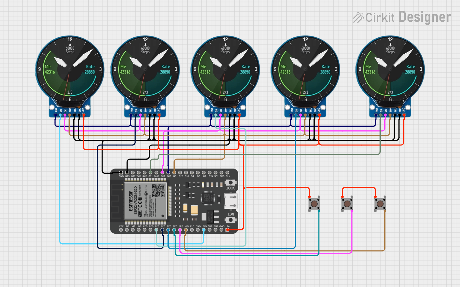 Open Project in Cirkit Designer
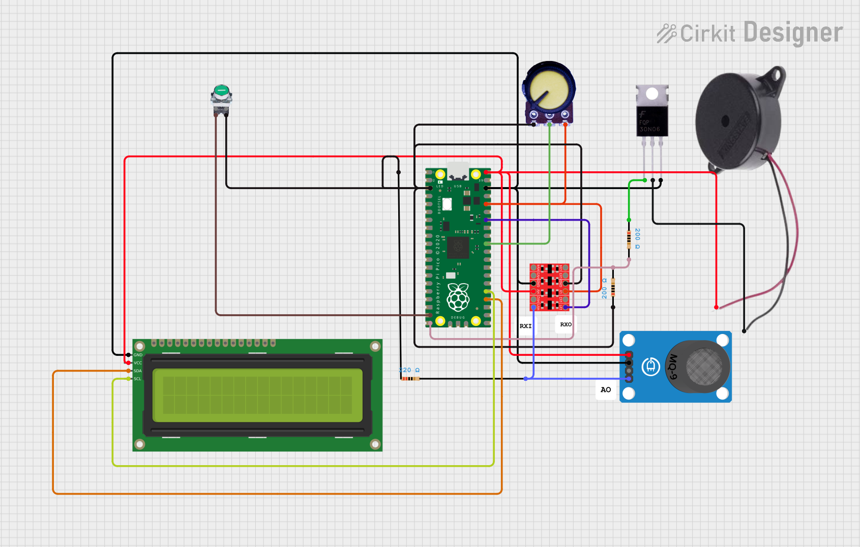 Open Project in Cirkit Designer
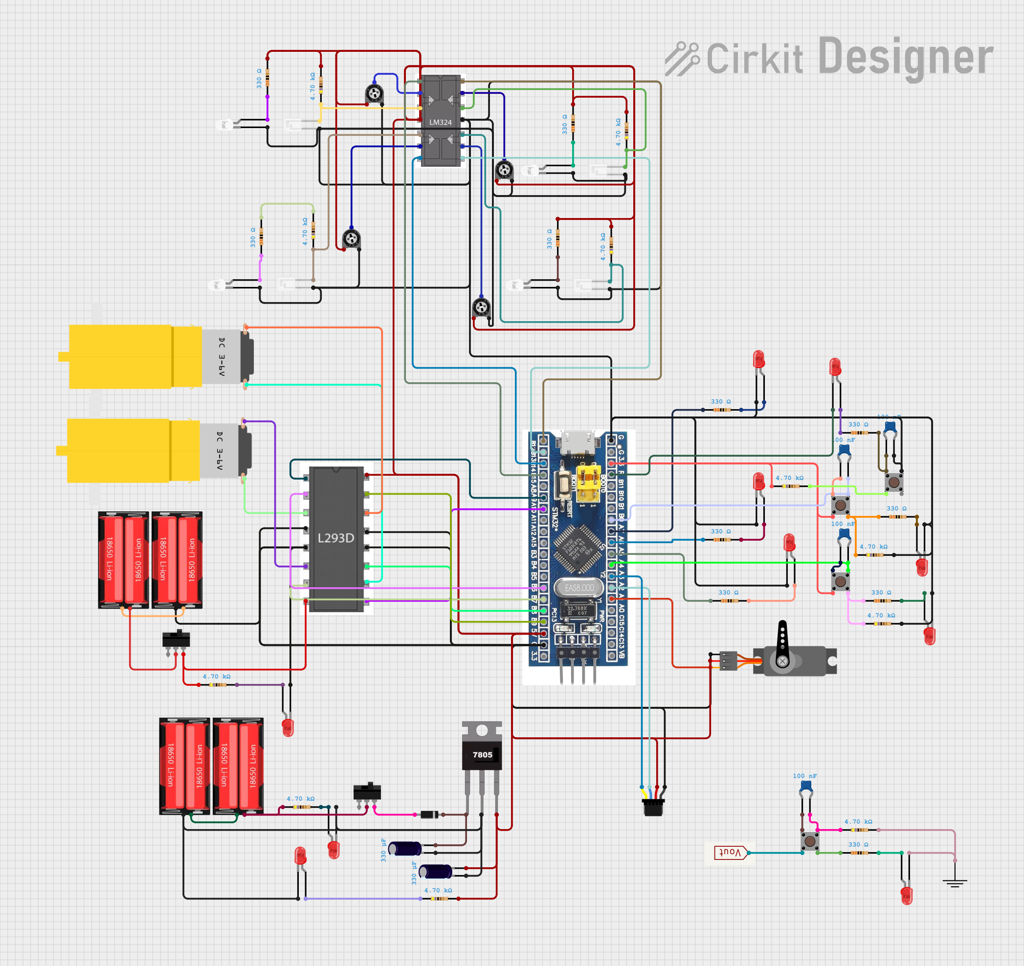 Open Project in Cirkit Designer
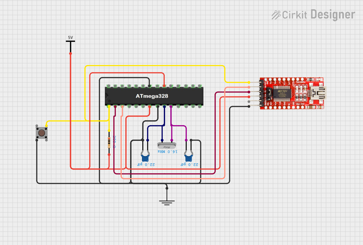 Open Project in Cirkit Designer
Explore Projects Built with PIC16F913
Open Project in Cirkit DesignerOpen Project in Cirkit DesignerOpen Project in Cirkit DesignerOpen Project in Cirkit DesignerCommon Applications
- Sensor interfacing and data acquisition
- Motor control and automation
- Low-power embedded systems
- Consumer electronics
- Educational and prototyping projects
Technical Specifications
Key Features
- Core Architecture: 8-bit
- Instruction Set: 14-bit
- Program Memory: 1K words (Flash)
- RAM: 128 bytes
- EEPROM: 256 bytes
- Operating Voltage: 2.0V to 5.5V
- Clock Speed: Up to 8 MHz (internal oscillator)
- I/O Pins: 22 (multiplexed with peripherals)
- Timers: 3 (Timer0, Timer1, Timer2)
- ADC: 10-bit, up to 11 channels
- Comparators: 2
- Watchdog Timer: Yes
- Power-Saving Modes: Sleep mode
- Package Options: PDIP, SOIC, SSOP, QFN
Pin Configuration
The PIC16F913 is available in a 28-pin package. Below is the pin configuration and description:
| Pin Number | Pin Name | Function |
|---|---|---|
| 1 | MCLR/VPP | Master Clear (Reset) / Programming Voltage |
| 2 | RA0/AN0 | Analog Input 0 / Digital I/O |
| 3 | RA1/AN1 | Analog Input 1 / Digital I/O |
| 4 | RA2/AN2/VREF- | Analog Input 2 / Voltage Reference (-) |
| 5 | RA3/AN3/VREF+ | Analog Input 3 / Voltage Reference (+) |
| 6 | RA4/T0CKI | Digital I/O / Timer0 Clock Input |
| 7 | RA5/AN4 | Analog Input 4 / Digital I/O |
| 8 | VSS | Ground |
| 9 | OSC1/CLKIN | Oscillator Input / Clock Input |
| 10 | OSC2/CLKOUT | Oscillator Output / Clock Output |
| 11 | RC0/T1OSO | Digital I/O / Timer1 Oscillator Output |
| 12 | RC1/T1OSI | Digital I/O / Timer1 Oscillator Input |
| 13 | RC2/CCP1 | Digital I/O / PWM Output |
| 14 | RC3/SCK/SCL | Digital I/O / SPI Clock / I2C Clock |
| 15 | RC4/SDI/SDA | Digital I/O / SPI Data In / I2C Data |
| 16 | RC5/SDO | Digital I/O / SPI Data Out |
| 17 | RC6/TX/CK | Digital I/O / UART Transmit / Clock |
| 18 | RC7/RX/DT | Digital I/O / UART Receive / Data |
| 19 | VDD | Positive Supply Voltage |
| 20 | RB0/INT | Digital I/O / External Interrupt |
| 21 | RB1 | Digital I/O |
| 22 | RB2 | Digital I/O |
| 23 | RB3/PGM | Digital I/O / Low-Voltage Programming |
| 24 | RB4 | Digital I/O |
| 25 | RB5 | Digital I/O |
| 26 | RB6/PGC | Digital I/O / Programming Clock |
| 27 | RB7/PGD | Digital I/O / Programming Data |
| 28 | VSS | Ground |
Usage Instructions
Using the PIC16F913 in a Circuit
- Power Supply: Connect the VDD pin to a 5V power source and the VSS pins to ground.
- Oscillator Configuration: Connect an external crystal oscillator to the OSC1 and OSC2 pins, or configure the internal oscillator via software.
- Reset Pin: Connect the MCLR pin to a pull-up resistor (typically 10kΩ) to VDD for normal operation. For programming, apply the required voltage to this pin.
- I/O Pins: Configure the I/O pins as input or output in the software. Use analog pins for ADC functionality.
- Programming: Use an ICSP (In-Circuit Serial Programming) tool to program the microcontroller via the PGC and PGD pins.
Example: Interfacing with an LED
Below is an example of how to blink an LED connected to pin RA0 using the PIC16F913:
// Configuration bits
#pragma config FOSC = INTRCIO  // Internal oscillator, I/O function on RA6/RA7
#pragma config WDTE = OFF      // Watchdog Timer disabled
#pragma config PWRTE = ON      // Power-up Timer enabled
#pragma config MCLRE = ON      // MCLR pin enabled
#pragma config CP = OFF        // Code protection disabled
#pragma config CPD = OFF       // Data code protection disabled
#pragma config BOREN = ON      // Brown-out Reset enabled
#pragma config IESO = OFF      // Internal/External Oscillator Switchover disabled
#pragma config FCMEN = OFF     // Fail-Safe Clock Monitor disabled

#include <xc.h>

#define _XTAL_FREQ 4000000  // Define the clock frequency (4 MHz)

void main(void) {
    TRISA0 = 0;  // Set RA0 as output
    while (1) {
        RA0 = 1;  // Turn on LED
        __delay_ms(500);  // Delay for 500 ms
        RA0 = 0;  // Turn off LED
        __delay_ms(500);  // Delay for 500 ms
    }
}
Best Practices
- Use decoupling capacitors (e.g., 0.1 µF) near the VDD and VSS pins to reduce noise.
- Avoid leaving unused pins floating; configure them as outputs or connect them to ground.
- Use proper pull-up or pull-down resistors for input pins to ensure stable operation.
- When using the ADC, ensure the reference voltage is stable and within the specified range.
Troubleshooting and FAQs
Common Issues
Microcontroller Not Responding:
- Ensure the power supply voltage is within the operating range (2.0V to 5.5V).
- Verify the MCLR pin is properly connected to a pull-up resistor.
- Check the oscillator configuration and ensure the clock source is functioning.
ADC Not Working:
- Confirm the analog input pins are configured correctly in the software.
- Ensure the reference voltage is stable and properly connected.
Programming Errors:
- Verify the ICSP connections (PGC, PGD, and MCLR).
- Ensure the programmer supports the PIC16F913 and is configured correctly.
FAQs
Q: Can I use the internal oscillator for my application?
A: Yes, the PIC16F913 includes an internal oscillator that can operate up to 8 MHz. It is suitable for most applications, but for precise timing, an external crystal oscillator is recommended.
Q: How do I reduce power consumption?
A: Use the sleep mode to minimize power consumption during idle periods. Additionally, disable unused peripherals in the software.
Q: What is the maximum current the I/O pins can source or sink?
A: Each I/O pin can source or sink up to 25 mA, with a total maximum current of 200 mA for all pins combined.
This concludes the documentation for the PIC16F913 microcontroller.