How to Use Adafruit WINC1500 (PCB Antenna) Breakout: Examples, Pinouts, and Specs
Introduction
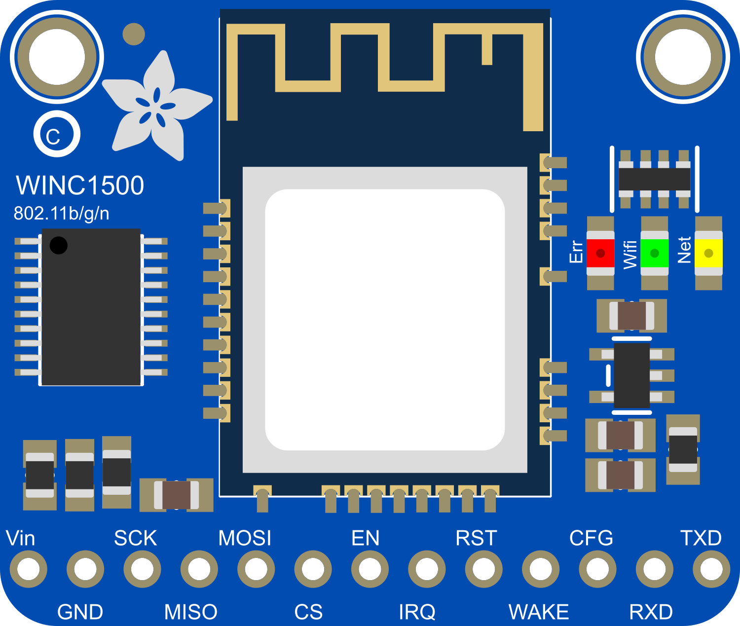
The Adafruit WINC1500 (PCB Antenna) Breakout is a compact Wi-Fi module that enables wireless connectivity for a wide range of Internet of Things (IoT) projects. Based on the Microchip WINC1500 chip, this breakout board is designed for ease of integration with microcontrollers such as the Arduino UNO. The onboard PCB antenna makes it a self-contained solution for adding Wi-Fi functionality without the need for external antennas.
Explore Projects Built with Adafruit WINC1500 (PCB Antenna) Breakout
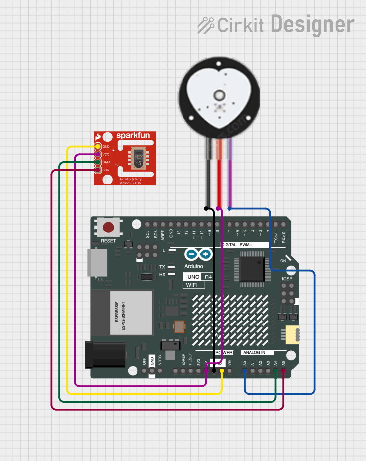
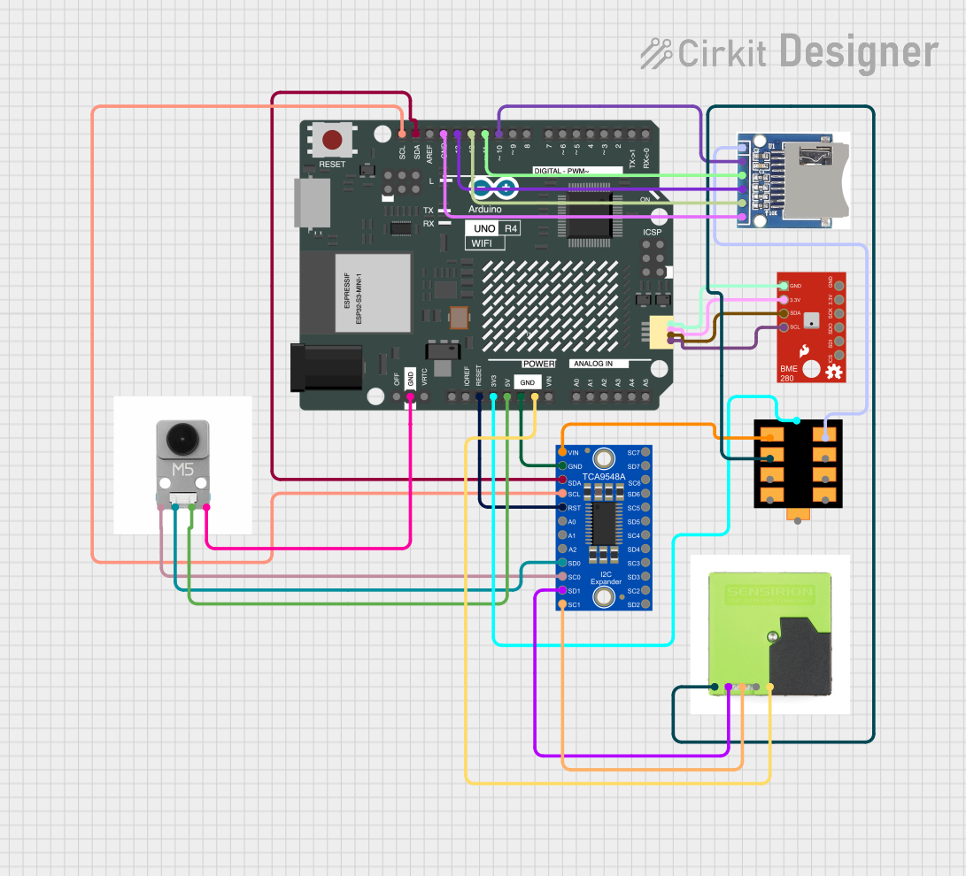
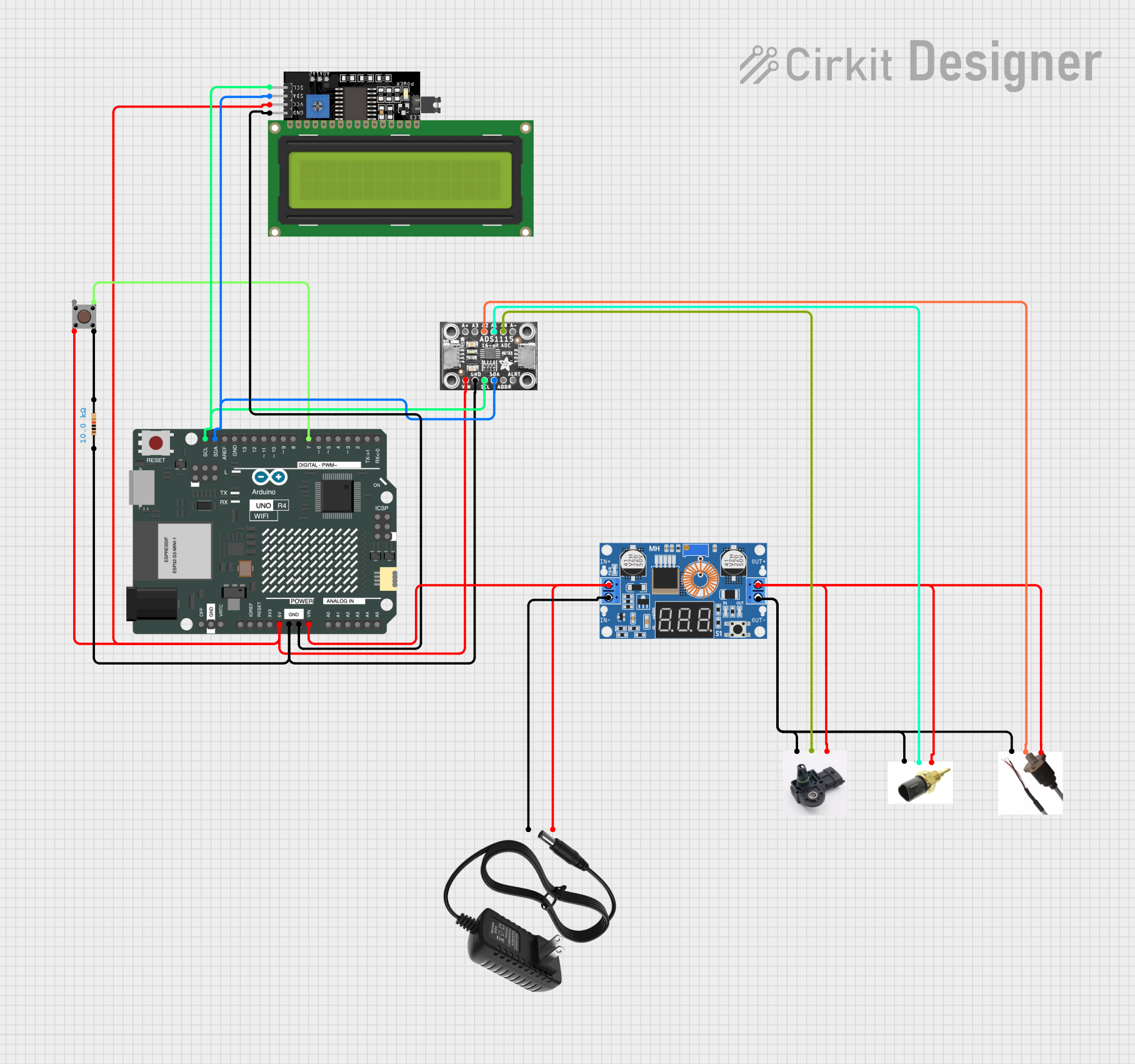
Explore Projects Built with Adafruit WINC1500 (PCB Antenna) Breakout
Common Applications and Use Cases
- IoT devices requiring internet connectivity
- Wireless sensor networks
- Remote data logging
- Home automation systems
- Wearable electronics
Technical Specifications
Key Technical Details
- Operating Voltage: 3.3V
- Interface: SPI
- Wi-Fi Protocols: 802.11 b/g/n
- Frequency Band: 2.4 GHz
- Security Protocols: WEP, WPA/WPA2 PSK/Enterprise
- Integrated TCP/IP protocol stack
- PCB Antenna: Onboard
Pin Configuration and Descriptions
| Pin Number | Name | Description |
|---|---|---|
| 1 | VIN | 3.3V Power Supply Input |
| 2 | GND | Ground |
| 3 | EN | Chip Enable (Active High) |
| 4 | RST | Reset (Active Low) |
| 5 | SCK | SPI Clock |
| 6 | MISO | SPI Master In Slave Out |
| 7 | MOSI | SPI Master Out Slave In |
| 8 | CS | SPI Chip Select (Active Low) |
| 9 | IRQ | Interrupt Request (Active Low) |
| 10 | 3V3 | 3.3V Output from Onboard Regulator |
Usage Instructions
How to Use the Component in a Circuit
- Power Supply: Connect the VIN pin to a 3.3V supply, and the GND pin to the ground of your power source.
- SPI Interface: Connect the SCK, MISO, MOSI, and CS pins to the corresponding SPI pins on your microcontroller.
- Control Pins: Connect the EN pin to a digital output on your microcontroller to enable the chip. The RST pin can be connected to another digital output for resetting the module.
- IRQ Pin: The IRQ pin can be connected to an interrupt-capable pin on your microcontroller to handle asynchronous events.
Important Considerations and Best Practices
- Ensure that the power supply is stable and does not exceed 3.3V, as higher voltages can damage the module.
- Use a level shifter if you are interfacing with a 5V microcontroller like the Arduino UNO.
- Keep the SPI lines as short as possible to prevent signal degradation.
- Avoid placing the module near metal objects or surfaces that could interfere with the antenna's signal.
Example Code for Arduino UNO
#include <SPI.h>
#include <WiFi101.h>

// Your network SSID and password
char ssid[] = "your_network_SSID";
char pass[] = "your_password";

void setup() {
  // Initialize serial communication
  Serial.begin(9600);

  // Check for the presence of the shield
  if (WiFi.status() == WL_NO_SHIELD) {
    Serial.println("WiFi shield not present");
    // Don't continue if the shield is not present
    while (true);
  }

  // Attempt to connect to WiFi network
  while (WiFi.begin(ssid, pass) != WL_CONNECTED) {
    Serial.print("Attempting to connect to SSID: ");
    Serial.println(ssid);
    // Wait 10 seconds before retrying
    delay(10000);
  }

  Serial.println("Connected to wifi");
  printWiFiStatus();
}

void loop() {
  // Nothing here for now.
}

void printWiFiStatus() {
  // Print the SSID of the network you're attached to
  Serial.print("SSID: ");
  Serial.println(WiFi.SSID());

  // Print your board's IP address
  IPAddress ip = WiFi.localIP();
  Serial.print("IP Address: ");
  Serial.println(ip);

  // Print the received signal strength
  long rssi = WiFi.RSSI();
  Serial.print("Signal strength (RSSI):");
  Serial.print(rssi);
  Serial.println(" dBm");
}
Troubleshooting and FAQs
Common Issues Users Might Face
- Module not responding: Ensure that the module is correctly powered and that the SPI connections are secure.
- Unable to connect to Wi-Fi: Verify that the SSID and password are correct and that the Wi-Fi network is within range.
- Intermittent connectivity: Check for sources of interference and ensure the antenna is not obstructed.
Solutions and Tips for Troubleshooting
- Power issues: Use a multimeter to check that the VIN pin is receiving 3.3V.
- SPI communication: Use an oscilloscope to verify that the SPI signals are clean and without excessive noise.
- Reset the module: If the module is unresponsive, try toggling the RST pin to reset it.
FAQs
Q: Can I use the Adafruit WINC1500 with a 5V microcontroller? A: Yes, but you will need to use a level shifter to convert the 5V signals to 3.3V to avoid damaging the module.
Q: How can I extend the range of the onboard antenna? A: For extended range, consider using an external antenna version of the WINC1500 breakout board.
Q: Does the WINC1500 support 5 GHz Wi-Fi bands? A: No, the WINC1500 chip only supports the 2.4 GHz Wi-Fi band.
Q: Can I use this module with battery power? A: Yes, as long as the battery can provide a stable 3.3V output. Consider using a voltage regulator if necessary.