How to Use ProtoSnap - Pro Mini - FTDI: Examples, Pinouts, and Specs
Introduction
The ProtoSnap - Pro Mini - FTDI is an innovative prototyping platform that integrates an Arduino Pro Mini with an FTDI (Future Technology Devices International) USB-to-serial programming interface. This combination simplifies the process of developing, programming, and testing Arduino-based projects by providing a seamless connection between the microcontroller and a computer for programming and serial communication.
Explore Projects Built with ProtoSnap - Pro Mini - FTDI

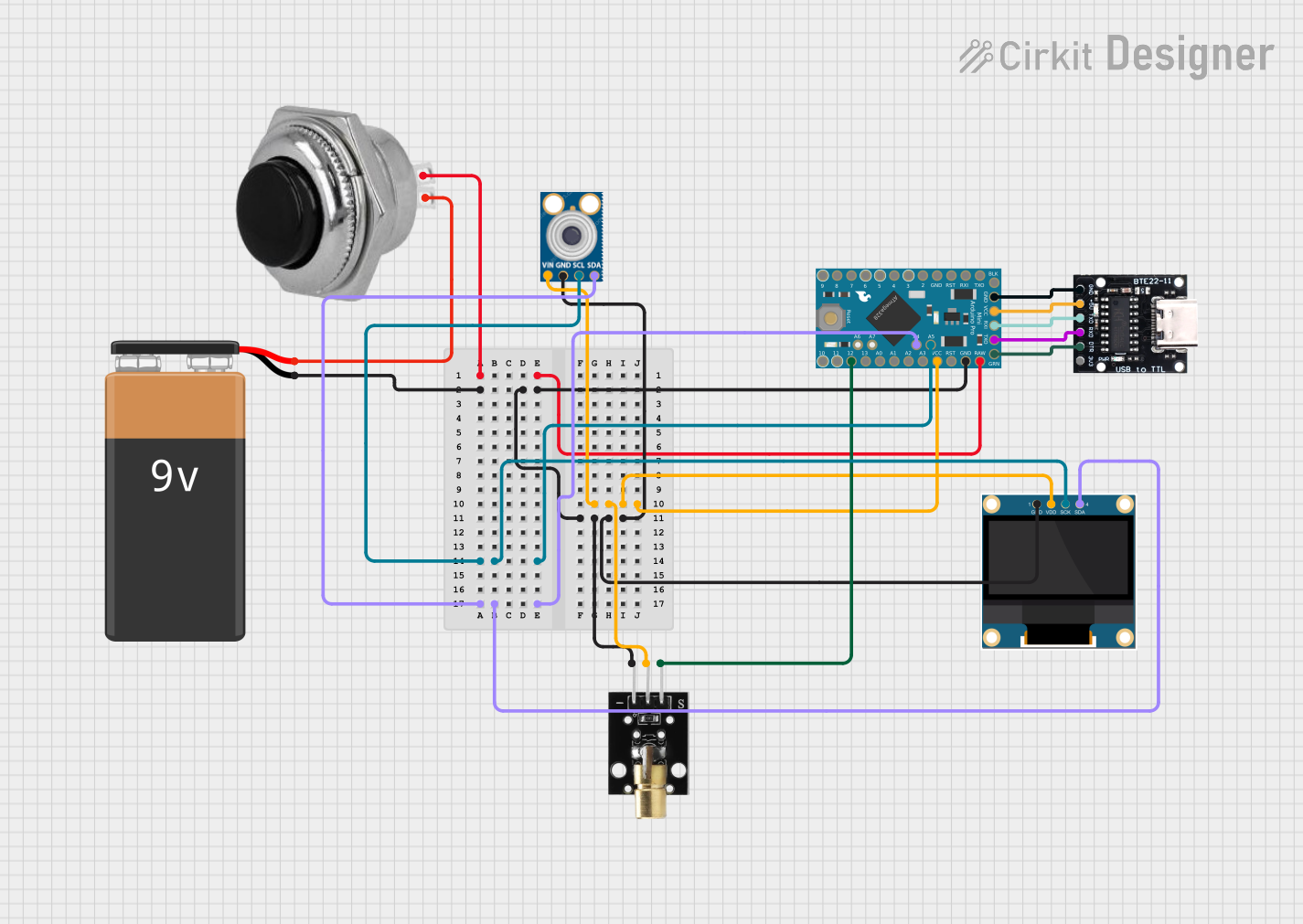
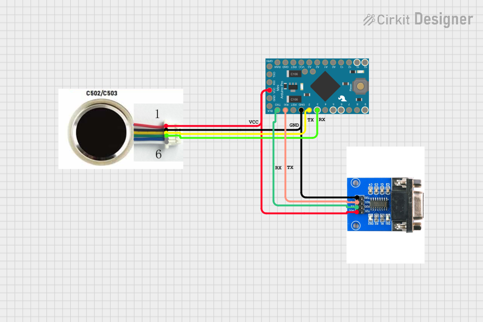
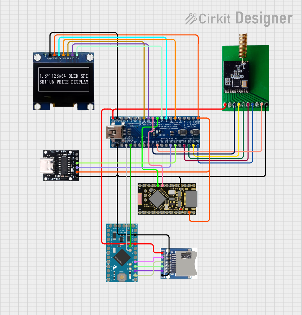
Explore Projects Built with ProtoSnap - Pro Mini - FTDI
Common Applications and Use Cases
- Rapid prototyping of microcontroller-based projects
- Educational purposes for learning electronics and programming
- DIY electronics projects
- Robotics and automation systems
- Wearable electronics
Technical Specifications
Key Technical Details
- Microcontroller: ATmega328
- Operating Voltage: 3.3V or 5V (depending on the model)
- Input Voltage (recommended): 5V via FTDI
- Digital I/O Pins: 14 (of which 6 provide PWM output)
- Analog Input Pins: 6
- DC Current per I/O Pin: 40 mA
- Flash Memory: 32 KB (ATmega328) of which 0.5 KB used by bootloader
- SRAM: 2 KB (ATmega328)
- EEPROM: 1 KB (ATmega328)
- Clock Speed: 8 MHz (3.3V model) or 16 MHz (5V model)
Pin Configuration and Descriptions
| Pin Number | Function | Description |
|---|---|---|
| 1 | RX | Receive pin for serial communication |
| 2 | TX | Transmit pin for serial communication |
| 3 to 8 | Digital Pins | General purpose digital I/O |
| 9 | PWM | PWM output capable pin |
| 10 to 13 | Digital Pins | General purpose digital I/O |
| 14 | A0 | Analog input pin 0 |
| 15 | A1 | Analog input pin 1 |
| ... | ... | ... |
| 19 | A5 | Analog input pin 5 |
| 20 | AREF | Analog reference voltage for the ADC |
| 21 | GND | Ground |
| 22 | RESET | Reset pin, active low |
| 23 | 3V3/5V | Operating voltage (depends on the model) |
| 24 | VCC | Power supply for the microcontroller |
| 25 | GND | Ground |
| 26 | RAW | Raw voltage input for onboard voltage regulator |
Usage Instructions
How to Use the Component in a Circuit
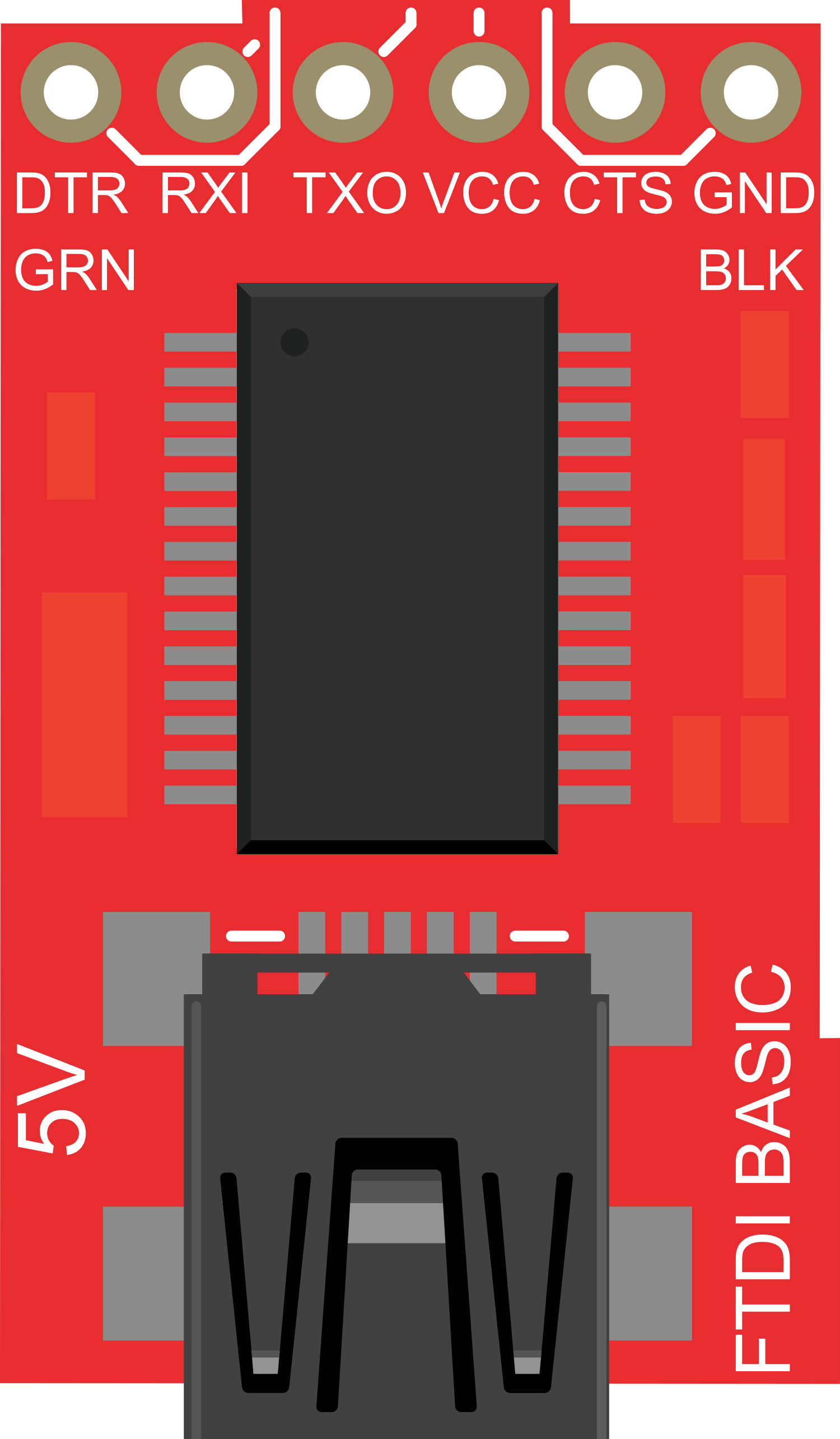
Connecting to a Computer:
- Connect the FTDI interface of the ProtoSnap - Pro Mini to a USB port on your computer using a mini-USB cable.
- Ensure that the correct drivers for the FTDI chip are installed on your computer.
Programming the Arduino Pro Mini:
- Open the Arduino IDE on your computer.
- Select the correct board (Arduino Pro Mini) and processor (ATmega328) from the Tools menu.
- Choose the correct port that corresponds to the FTDI interface.
- Write or open the Arduino sketch you wish to upload.
- Click the upload button in the Arduino IDE to program the Pro Mini.
Using External Components:
- Connect external components such as sensors, LEDs, or motors to the appropriate pins on the Pro Mini, taking care to match the voltage levels and current requirements.
Important Considerations and Best Practices
- Always ensure that the power supply voltage matches the operating voltage of your ProtoSnap - Pro Mini (3.3V or 5V).
- Do not exceed the maximum current rating for each I/O pin (40 mA) to prevent damage to the microcontroller.
- Use external power sources when connecting components that require more current than the Pro Mini can provide.
- Disconnect the Pro Mini from the USB port when working on the circuit to avoid short circuits or electrical shocks.
Troubleshooting and FAQs
Common Issues Users Might Face
The Pro Mini is not recognized by the computer:
- Check the USB cable and ensure it is properly connected.
- Verify that the FTDI drivers are installed on your computer.
- Try using a different USB port or a different computer.
Sketch fails to upload:
- Ensure that the correct board and processor are selected in the Arduino IDE.
- Check the selected port and make sure it corresponds to the FTDI interface.
- Press the reset button on the Pro Mini just before uploading the sketch.
External components are not working as expected:
- Verify that all connections are secure and correctly wired.
- Check that the power supply is adequate for the external components.
- Ensure that the code uploaded to the Pro Mini is correct and free of errors.
Solutions and Tips for Troubleshooting
- Double-check all connections and wiring against the circuit diagram.
- Use a multimeter to verify voltages and continuity in the circuit.
- Review the code for any logical errors or incorrect pin assignments.
- Consult online forums and communities for advice if the issue persists.
Example Code for Arduino UNO
// Blink an LED connected to pin 13 of the ProtoSnap - Pro Mini

void setup() {
  pinMode(13, OUTPUT); // Initialize pin 13 as an output
}

void loop() {
  digitalWrite(13, HIGH); // Turn the LED on
  delay(1000);            // Wait for a second
  digitalWrite(13, LOW);  // Turn the LED off
  delay(1000);            // Wait for a second
}
Note: The above code is for illustrative purposes. The ProtoSnap - Pro Mini - FTDI is similar to the Arduino Pro Mini and can be programmed using the Arduino IDE with the appropriate board selection.