Cirkit Designer
Your all-in-one circuit design IDE
Home /
Component Documentation
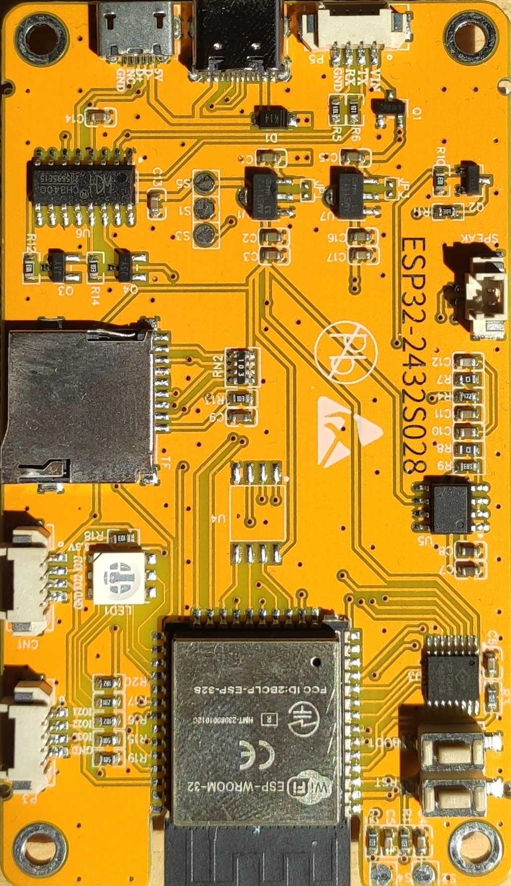
How to Use ESP32-2432S028: Examples, Pinouts, and Specs
Introduction
The ESP32-2432S028 is a powerful microcontroller module designed for IoT applications and embedded systems. It features a dual-core processor with integrated Wi-Fi and Bluetooth capabilities, making it ideal for projects requiring wireless communication and high processing power. This module is widely used in smart home devices, industrial automation, wearable electronics, and other connected systems.
Explore Projects Built with ESP32-2432S028
ESP32-S3 Based Smart IoT Distance Sensor with Ethernet Connectivity

This circuit features an ESP32-S3 microcontroller interfaced with a KY-019 Relay module, a VL53L1X time-of-flight sensor, and a W5500 Ethernet module. The ESP32-S3 controls the relay and communicates with the VL53L1X sensor via I2C, as well as with the network through the Ethernet module. An AC source is converted to DC for powering the components, and a micro USB connection is used to trigger the relay.
ESP32 and W5500 Ethernet Module-Based Smart Weather Station with Battery-Powered Motor
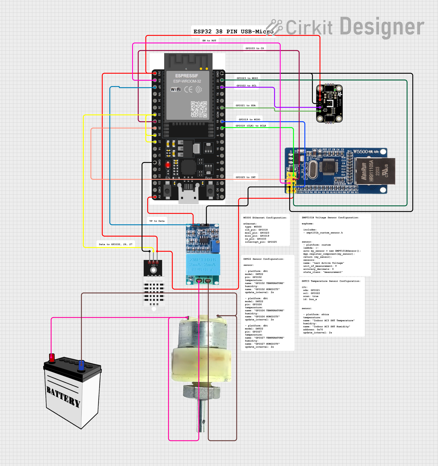
This circuit integrates an ESP32 microcontroller with various sensors and an Ethernet module for data acquisition and network communication. It includes a DHT22 and SHTC3 sensor for environmental monitoring, a ZMPT101B for voltage measurement, and a 12V geared motor controlled by a 12V battery. The ESP32 handles sensor data and communicates via the W5500 Ethernet module.
Cellular-Connected ESP32-CAM with Real-Time Clock and Isolated Control

This circuit integrates a LilyGo-SIM7000G module with an RTC DS3231 for timekeeping, interfaced via I2C (SCL and SDA lines). An 8-Channel OPTO-COUPLER is used to isolate and interface external signals with the LilyGo-SIM7000G's GPIOs. Power is managed by a Buck converter, which steps down voltage from a DC Power Source to supply the ESP32-CAM and LilyGo-SIM7000G modules, as well as the OPTO-COUPLER.
ESP32-S3 Based Automated Watering System with Ultrasonic Sensing and Data Logging

This circuit features an ESP32-S3 microcontroller connected to various peripherals including an HC-SR04 ultrasonic sensor, a water flow sensor, an OLED display, a DS3231 real-time clock (RTC), an SD card module, a water pump, a two-channel relay, and a valve solenoid. The ESP32-S3 manages sensor readings, data logging, and controls the water pump and valve via the relay based on sensor inputs. The circuit is designed for monitoring and controlling water flow, likely in an automated irrigation or fluid management system.
Explore Projects Built with ESP32-2432S028
ESP32-S3 Based Smart IoT Distance Sensor with Ethernet Connectivity
This circuit features an ESP32-S3 microcontroller interfaced with a KY-019 Relay module, a VL53L1X time-of-flight sensor, and a W5500 Ethernet module. The ESP32-S3 controls the relay and communicates with the VL53L1X sensor via I2C, as well as with the network through the Ethernet module. An AC source is converted to DC for powering the components, and a micro USB connection is used to trigger the relay.
ESP32 and W5500 Ethernet Module-Based Smart Weather Station with Battery-Powered Motor
This circuit integrates an ESP32 microcontroller with various sensors and an Ethernet module for data acquisition and network communication. It includes a DHT22 and SHTC3 sensor for environmental monitoring, a ZMPT101B for voltage measurement, and a 12V geared motor controlled by a 12V battery. The ESP32 handles sensor data and communicates via the W5500 Ethernet module.
Cellular-Connected ESP32-CAM with Real-Time Clock and Isolated Control
This circuit integrates a LilyGo-SIM7000G module with an RTC DS3231 for timekeeping, interfaced via I2C (SCL and SDA lines). An 8-Channel OPTO-COUPLER is used to isolate and interface external signals with the LilyGo-SIM7000G's GPIOs. Power is managed by a Buck converter, which steps down voltage from a DC Power Source to supply the ESP32-CAM and LilyGo-SIM7000G modules, as well as the OPTO-COUPLER.
ESP32-S3 Based Automated Watering System with Ultrasonic Sensing and Data Logging
This circuit features an ESP32-S3 microcontroller connected to various peripherals including an HC-SR04 ultrasonic sensor, a water flow sensor, an OLED display, a DS3231 real-time clock (RTC), an SD card module, a water pump, a two-channel relay, and a valve solenoid. The ESP32-S3 manages sensor readings, data logging, and controls the water pump and valve via the relay based on sensor inputs. The circuit is designed for monitoring and controlling water flow, likely in an automated irrigation or fluid management system.
Common Applications
- IoT devices and smart home automation
- Wireless sensor networks
- Wearable technology
- Industrial control systems
- Robotics and drones
- Real-time data monitoring and logging
Technical Specifications
Key Technical Details
| Parameter | Specification |
|---|---|
| Processor | Dual-core Xtensa® 32-bit LX6 CPU |
| Clock Speed | Up to 240 MHz |
| Flash Memory | 4 MB (external) |
| SRAM | 520 KB |
| Wireless Connectivity | Wi-Fi 802.11 b/g/n, Bluetooth v4.2 |
| Operating Voltage | 3.3V |
| GPIO Pins | 28 |
| Communication Protocols | UART, SPI, I2C, I2S, PWM, ADC, DAC |
| ADC Channels | 18 (12-bit resolution) |
| Operating Temperature | -40°C to +85°C |
| Dimensions | 2.8 x 2.4 cm |
Pin Configuration and Descriptions
| Pin Number | Pin Name | Description |
|---|---|---|
| 1 | 3V3 | 3.3V Power Supply |
| 2 | GND | Ground |
| 3 | EN | Enable Pin (Active High) |
| 4 | IO0 | GPIO0, Boot Mode Selection |
| 5 | IO1 | GPIO1, UART TXD |
| 6 | IO2 | GPIO2, General Purpose I/O |
| 7 | IO3 | GPIO3, UART RXD |
| 8 | IO4 | GPIO4, PWM/ADC/DAC |
| 9 | IO5 | GPIO5, SPI SCK |
| 10 | IO12 | GPIO12, Touch Sensor/ADC |
| 11 | IO13 | GPIO13, Touch Sensor/ADC |
| 12 | IO14 | GPIO14, SPI MISO |
| 13 | IO15 | GPIO15, SPI MOSI |
| 14 | IO16 | GPIO16, UART RXD |
| 15 | IO17 | GPIO17, UART TXD |
| 16 | IO18 | GPIO18, SPI SCK |
| 17 | IO19 | GPIO19, I2C SDA |
| 18 | IO21 | GPIO21, I2C SCL |
| 19 | IO22 | GPIO22, PWM/ADC |
| 20 | IO23 | GPIO23, PWM/ADC |
| 21 | IO25 | GPIO25, DAC Channel 1 |
| 22 | IO26 | GPIO26, DAC Channel 2 |
| 23 | IO27 | GPIO27, PWM/ADC |
| 24 | IO32 | GPIO32, ADC Channel |
| 25 | IO33 | GPIO33, ADC Channel |
| 26 | IO34 | GPIO34, ADC Channel (Input Only) |
| 27 | IO35 | GPIO35, ADC Channel (Input Only) |
| 28 | IO36 | GPIO36, ADC Channel (Input Only) |
Usage Instructions
How to Use the ESP32-2432S028 in a Circuit
- Power Supply: Connect the 3V3 pin to a 3.3V power source and GND to ground.
- Programming: Use a USB-to-serial adapter to connect the module to your computer. Ensure the EN pin is pulled high to enable the module.
- Boot Mode: To upload code, pull GPIO0 low during reset to enter bootloader mode.
- GPIO Usage: Configure GPIO pins as input or output in your code. Use ADC pins for analog input and DAC pins for analog output.
- Wireless Communication: Use the built-in Wi-Fi and Bluetooth libraries to establish wireless connections.
Important Considerations
- Voltage Levels: Ensure all GPIO pins operate at 3.3V logic levels. Using higher voltages may damage the module.
- Power Supply: Provide a stable 3.3V power source with sufficient current (at least 500 mA).
- Antenna Placement: Avoid placing metal objects near the onboard antenna to ensure optimal wireless performance.
- Heat Management: If operating at high loads, consider adding a heatsink to prevent overheating.
Example Code for Arduino UNO
Below is an example of using the ESP32-2432S028 to connect to a Wi-Fi network and print the IP address:
#include <WiFi.h> // Include the Wi-Fi library for ESP32

const char* ssid = "Your_SSID";       // Replace with your Wi-Fi SSID
const char* password = "Your_Password"; // Replace with your Wi-Fi password

void setup() {
  Serial.begin(115200); // Initialize serial communication at 115200 baud
  delay(1000);          // Wait for a second to stabilize

  Serial.println("Connecting to Wi-Fi...");
  WiFi.begin(ssid, password); // Start Wi-Fi connection

  while (WiFi.status() != WL_CONNECTED) {
    delay(500); // Wait until the connection is established
    Serial.print(".");
  }

  Serial.println("\nWi-Fi connected!");
  Serial.print("IP Address: ");
  Serial.println(WiFi.localIP()); // Print the assigned IP address
}

void loop() {
  // Add your main code here
}
Troubleshooting and FAQs
Common Issues
Wi-Fi Connection Fails:
- Ensure the SSID and password are correct.
- Check if the router is within range and functioning properly.
- Verify that the module is powered correctly.
Code Upload Fails:
- Ensure GPIO0 is pulled low during reset to enter bootloader mode.
- Check the USB-to-serial adapter connections.
- Install the correct USB driver for your adapter.
Module Overheating:
- Verify that the power supply provides sufficient current.
- Reduce the processing load or add a heatsink.
Unstable Wireless Performance:
- Avoid placing the module near sources of interference (e.g., microwaves).
- Ensure the onboard antenna is not obstructed.
Tips for Troubleshooting
- Use a multimeter to check voltage levels on the power pins.
- Monitor the serial output for error messages during debugging.
- Update the ESP32 board package in the Arduino IDE to the latest version.
By following this documentation, you can effectively integrate the ESP32-2432S028 into your projects and troubleshoot common issues with ease.