
How to Use Adafruit DS2413 1-Wire Two GPIO Controller Breakout: Examples, Pinouts, and Specs
 Design with Adafruit DS2413 1-Wire Two GPIO Controller Breakout in Cirkit Designer
Introduction
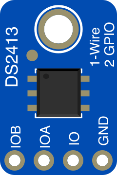
The Adafruit DS2413 1-Wire Two GPIO Controller Breakout (Part ID: 1551) is a compact and versatile breakout board featuring the DS2413 chip. This component provides two general-purpose input/output (GPIO) pins that communicate using the 1-Wire protocol. The 1-Wire interface allows for simple communication with microcontrollers using only a single data line, making it ideal for projects where pin availability is limited.
Explore Projects Built with Adafruit DS2413 1-Wire Two GPIO Controller Breakout
 Open Project in Cirkit Designer
 Open Project in Cirkit Designer
 Open Project in Cirkit Designer
 Open Project in Cirkit Designer
Explore Projects Built with Adafruit DS2413 1-Wire Two GPIO Controller Breakout
Open Project in Cirkit DesignerOpen Project in Cirkit DesignerOpen Project in Cirkit DesignerOpen Project in Cirkit DesignerCommon Applications and Use Cases
- Controlling LEDs, relays, or other low-power devices
- Reading the state of switches or sensors
- Expanding GPIO capabilities in microcontroller projects
- Applications requiring minimal wiring, such as home automation or IoT devices
Technical Specifications
The Adafruit DS2413 breakout board is designed for ease of use and integration. Below are the key technical details:
Key Specifications
| Parameter | Value |
|---|---|
| Communication Protocol | 1-Wire |
| GPIO Pins | 2 (individually configurable as input/output) |
| Operating Voltage | 3.3V to 5.5V |
| Maximum Sink Current | 20mA per GPIO pin |
| Operating Temperature | -40°C to +85°C |
| Dimensions | 20mm x 18mm x 2mm |
Pin Configuration and Descriptions
The breakout board has four main pins for connection:
| Pin Name | Description |
|---|---|
| VIN | Power input (3.3V to 5.5V) |
| GND | Ground connection |
| DQ | 1-Wire data line for communication |
| IOA/IOB | GPIO pins (IOA and IOB) for controlling or reading external devices |
Usage Instructions
The Adafruit DS2413 breakout board is straightforward to use in a circuit. Below are the steps and considerations for integrating it into your project.
How to Use the Component in a Circuit
- Power the Board: Connect the
VINpin to a 3.3V or 5V power source and theGNDpin to ground. - Connect the Data Line: Attach the
DQpin to the microcontroller's 1-Wire data pin. A pull-up resistor (typically 4.7kΩ) is required on the data line. - Configure GPIO Pins: Use the 1-Wire protocol to configure the GPIO pins (
IOAandIOB) as inputs or outputs. - Control Devices: Connect external devices (e.g., LEDs, relays, or sensors) to the GPIO pins. Ensure the current does not exceed 20mA per pin.
Important Considerations and Best Practices
- Pull-Up Resistor: Always include a pull-up resistor on the
DQline to ensure proper communication. - Current Limitation: Do not exceed the maximum sink current of 20mA per GPIO pin to avoid damaging the chip.
- 1-Wire Addressing: Each DS2413 chip has a unique 64-bit ROM address. Use this address to communicate with the specific device in multi-device setups.
- Decoupling Capacitor: Add a small decoupling capacitor (e.g., 0.1µF) between
VINandGNDto stabilize the power supply.
Example Code for Arduino UNO
Below is an example of how to use the Adafruit DS2413 breakout board with an Arduino UNO. This code demonstrates how to toggle the GPIO pins.
#include <OneWire.h>
#include <DS2413.h>

// Define the 1-Wire data pin
#define ONE_WIRE_BUS 2

// Initialize the OneWire and DS2413 objects
OneWire oneWire(ONE_WIRE_BUS);
DS2413 ds2413(&oneWire);

void setup() {
  Serial.begin(9600);
  Serial.println("Adafruit DS2413 Example");

  // Search for the DS2413 device
  if (!ds2413.begin()) {
    Serial.println("No DS2413 device found!");
    while (1); // Halt if no device is found
  }

  Serial.println("DS2413 device found!");
}

void loop() {
  // Set GPIO A high and GPIO B low
  if (ds2413.write(DS2413::PINS::IOA_HIGH | DS2413::PINS::IOB_LOW)) {
    Serial.println("GPIO A: HIGH, GPIO B: LOW");
  } else {
    Serial.println("Failed to write to DS2413");
  }

  delay(1000);

  // Set GPIO A low and GPIO B high
  if (ds2413.write(DS2413::PINS::IOA_LOW | DS2413::PINS::IOB_HIGH)) {
    Serial.println("GPIO A: LOW, GPIO B: HIGH");
  } else {
    Serial.println("Failed to write to DS2413");
  }

  delay(1000);
}
Troubleshooting and FAQs
Common Issues and Solutions
Device Not Detected
- Ensure the
DQpin is connected to the correct microcontroller pin. - Verify the pull-up resistor (4.7kΩ) is properly connected to the
DQline. - Check the power supply voltage (3.3V to 5.5V).
- Ensure the
GPIO Pins Not Responding
- Confirm the GPIO pins are correctly configured as input or output.
- Ensure the connected devices do not exceed the 20mA current limit.
Unstable Communication
- Add a decoupling capacitor (0.1µF) between
VINandGND. - Verify the pull-up resistor value is appropriate for the 1-Wire bus.
- Add a decoupling capacitor (0.1µF) between
FAQs
Q: Can I use multiple DS2413 devices on the same 1-Wire bus?
A: Yes, each DS2413 chip has a unique 64-bit ROM address, allowing multiple devices to coexist on the same bus.
Q: What is the maximum cable length for the 1-Wire bus?
A: The maximum cable length depends on factors like wire type and pull-up resistor value. Typically, lengths up to 30 meters are achievable with proper wiring.
Q: Can the GPIO pins source current?
A: No, the GPIO pins can only sink current (up to 20mA). Use external pull-up resistors if sourcing current is required.