How to Use UV Sensor (C): Examples, Pinouts, and Specs
Introduction
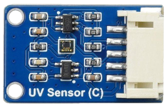
The UV Sensor (C), manufactured by Waveshare with part ID LTR390-UV-01, is a high-performance ultraviolet light sensor designed to detect UV light levels in the environment. This sensor is ideal for applications such as environmental monitoring, UV exposure measurement, and safety systems. It provides accurate and reliable UV intensity readings, making it a valuable component for projects requiring UV light detection.
The sensor is compact, easy to integrate into various systems, and supports I2C communication, making it compatible with microcontrollers like Arduino and Raspberry Pi.
Explore Projects Built with UV Sensor (C)
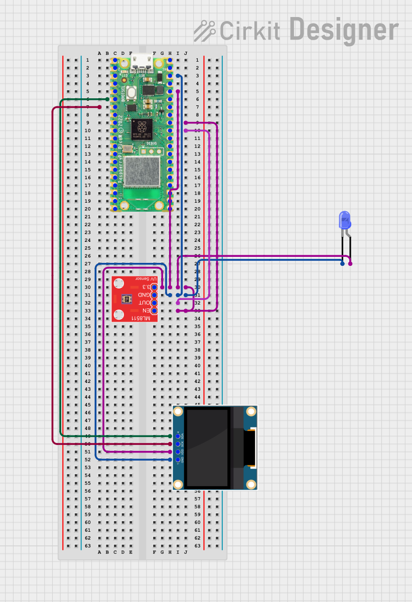
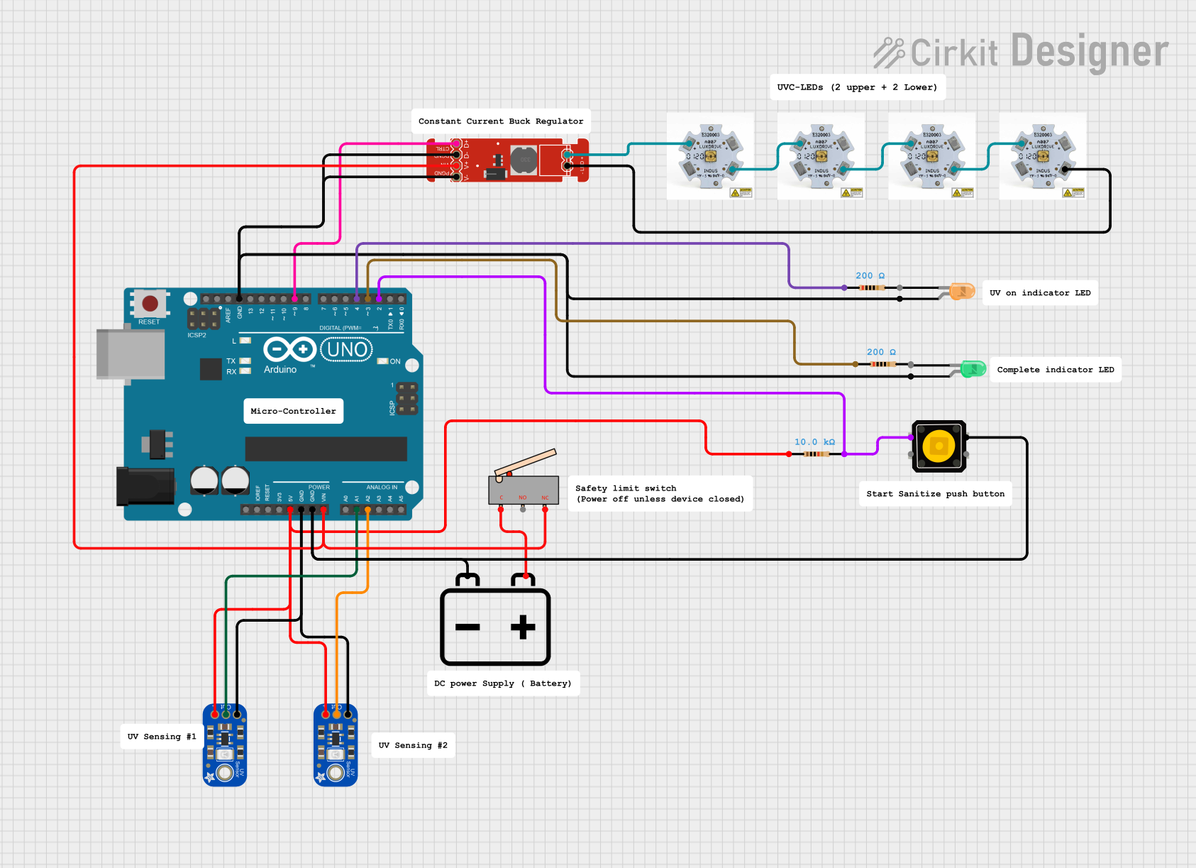
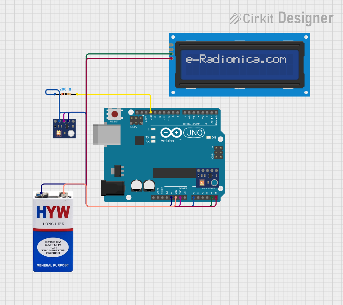

Explore Projects Built with UV Sensor (C)
Technical Specifications
Below are the key technical details of the UV Sensor (C):
| Parameter | Value |
|---|---|
| Manufacturer | Waveshare |
| Part ID | LTR390-UV-01 |
| Operating Voltage | 3.3V to 5V |
| Communication Protocol | I2C |
| UV Index Range | 0 to 15 |
| Operating Temperature | -40°C to 85°C |
| Spectral Range | 280 nm to 400 nm (UV-A and UV-B) |
| Dimensions | 19mm × 19mm |
Pin Configuration and Descriptions
The UV Sensor (C) has a 4-pin interface. The pinout is as follows:
| Pin | Name | Description |
|---|---|---|
| 1 | VCC | Power supply input (3.3V to 5V) |
| 2 | GND | Ground connection |
| 3 | SDA | I2C data line |
| 4 | SCL | I2C clock line |
Usage Instructions
How to Use the Component in a Circuit
- Power the Sensor: Connect the VCC pin to a 3.3V or 5V power source and the GND pin to the ground.
- I2C Communication: Connect the SDA and SCL pins to the corresponding I2C pins on your microcontroller. For an Arduino UNO:
- Connect SDA to A4.
- Connect SCL to A5.
- Pull-Up Resistors: Ensure that the I2C lines (SDA and SCL) have pull-up resistors (typically 4.7kΩ). Some breakout boards may already include these resistors.
- Install Libraries: If using Arduino, install the required libraries (e.g., Adafruit LTR390 library) for easy integration.
Example Arduino Code
Below is an example code snippet to read UV index data from the UV Sensor (C) using an Arduino UNO:
#include <Wire.h>
#include <Adafruit_LTR390.h>

// Create an instance of the LTR390 sensor
Adafruit_LTR390 ltr = Adafruit_LTR390();

void setup() {
  Serial.begin(9600); // Initialize serial communication
  while (!Serial) delay(10); // Wait for the serial monitor to open

  Serial.println("Initializing LTR390 UV Sensor...");

  // Initialize the sensor
  if (!ltr.begin()) {
    Serial.println("Failed to find LTR390 sensor! Check connections.");
    while (1) delay(10); // Halt execution if sensor is not found
  }

  Serial.println("LTR390 sensor initialized successfully.");
}

void loop() {
  // Check if the sensor is in UV mode
  if (ltr.getMode() != LTR390_MODE_UVS) {
    ltr.setMode(LTR390_MODE_UVS); // Set the sensor to UV mode
  }

  // Read UV index
  float uvIndex = ltr.readUVIndex();

  // Print UV index to the serial monitor
  Serial.print("UV Index: ");
  Serial.println(uvIndex);

  delay(1000); // Wait 1 second before the next reading
}
Important Considerations and Best Practices
- Power Supply: Ensure the sensor is powered within its operating voltage range (3.3V to 5V).
- I2C Address: The default I2C address of the sensor is
0x53. Verify this address if multiple I2C devices are connected. - UV Exposure: Avoid prolonged exposure of the sensor to intense UV light, as it may degrade the sensor's performance over time.
- Calibration: For precise measurements, consider calibrating the sensor based on your specific application and environment.
Troubleshooting and FAQs
Common Issues and Solutions
Sensor Not Detected
- Cause: Incorrect wiring or I2C address conflict.
- Solution: Double-check the wiring and ensure the I2C address matches the one in your code.
Incorrect UV Index Readings
- Cause: Improper calibration or environmental interference.
- Solution: Calibrate the sensor and ensure it is not exposed to stray light sources.
No Data Output
- Cause: Missing pull-up resistors on the I2C lines.
- Solution: Add 4.7kΩ pull-up resistors to the SDA and SCL lines if not already present.
FAQs
Q: Can the sensor measure visible light?
A: No, the LTR390-UV-01 is specifically designed to measure UV light in the 280 nm to 400 nm range.
Q: Is the sensor waterproof?
A: No, the sensor is not waterproof. Use appropriate enclosures for outdoor or humid environments.
Q: Can I use this sensor with a Raspberry Pi?
A: Yes, the sensor supports I2C communication and can be used with Raspberry Pi. Ensure you use the correct I2C pins and libraries.
Q: What is the maximum UV index the sensor can measure?
A: The sensor can measure UV index values in the range of 0 to 15.
By following this documentation, you can effectively integrate and use the UV Sensor (C) in your projects.