
How to Use 1S BMS 3.7V-4.2V : Examples, Pinouts, and Specs
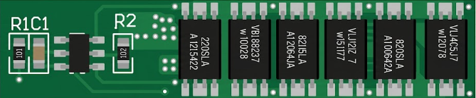
 Design with 1S BMS 3.7V-4.2V in Cirkit Designer
Introduction
The 1S BMS (Battery Management System) is a compact and efficient module designed to manage a single lithium-ion cell. It operates within a voltage range of 3.7V to 4.2V, ensuring the safe operation of the battery by providing protection against over-voltage, under-voltage, over-current, and short circuits. This component is essential for maintaining the health and longevity of lithium-ion batteries, making it a critical part of battery-powered devices.
Explore Projects Built with 1S BMS 3.7V-4.2V
 Open Project in Cirkit Designer
 Open Project in Cirkit Designer
 Open Project in Cirkit Designer
 Open Project in Cirkit Designer
Explore Projects Built with 1S BMS 3.7V-4.2V
Open Project in Cirkit DesignerOpen Project in Cirkit DesignerOpen Project in Cirkit DesignerOpen Project in Cirkit DesignerCommon Applications and Use Cases
- Power banks and portable chargers
- Single-cell lithium-ion battery packs
- Wearable devices and IoT gadgets
- Small robotics and DIY electronics projects
- LED lighting systems powered by lithium-ion cells
Technical Specifications
Below are the key technical details of the 1S BMS 3.7V-4.2V module:
| Parameter | Value |
|---|---|
| Operating Voltage Range | 3.7V to 4.2V |
| Maximum Charging Voltage | 4.25V ± 0.05V |
| Over-Discharge Voltage | 2.5V ± 0.1V |
| Maximum Continuous Current | 3A |
| Over-Current Protection | 6A ± 1A |
| Short Circuit Protection | Yes |
| Dimensions | ~20mm x 15mm x 3mm |
| Operating Temperature | -40°C to +85°C |
Pin Configuration and Descriptions
The 1S BMS module typically has four connection points:
| Pin Name | Description |
|---|---|
| B+ | Positive terminal of the lithium-ion battery |
| B- | Negative terminal of the lithium-ion battery |
| P+ | Positive terminal for the load or charging circuit |
| P- | Negative terminal for the load or charging circuit |
Usage Instructions
How to Use the 1S BMS in a Circuit
- Connect the Battery:
- Attach the positive terminal of the lithium-ion cell to the
B+pin. - Attach the negative terminal of the lithium-ion cell to the
B-pin.
- Attach the positive terminal of the lithium-ion cell to the
- Connect the Load or Charger:
- Connect the positive terminal of the load or charger to the
P+pin. - Connect the negative terminal of the load or charger to the
P-pin.
- Connect the positive terminal of the load or charger to the
- Verify Connections:
- Double-check all connections to ensure proper polarity and secure contacts.
- Power On:
- Once connected, the BMS will automatically manage the battery's charging and discharging processes.
Important Considerations and Best Practices
- Battery Compatibility: Ensure the lithium-ion cell used is rated for 3.7V nominal voltage and 4.2V maximum charging voltage.
- Heat Dissipation: Avoid exceeding the maximum continuous current rating (3A) to prevent overheating.
- Short Circuit Protection: While the module includes short circuit protection, always handle connections carefully to avoid accidental shorts.
- Charging Source: Use a charger that outputs a voltage within the module's supported range (typically 4.2V for lithium-ion cells).
- Testing: Before integrating the BMS into a final project, test it with a multimeter to confirm proper operation.
Example: Using the 1S BMS with an Arduino UNO
If you are powering an Arduino UNO with a lithium-ion battery and the 1S BMS, connect the P+ and P- pins to the Arduino's VIN and GND pins, respectively. Below is an example code snippet to monitor the battery voltage using the Arduino's analog input:
// Define the analog pin connected to the battery voltage divider
const int batteryPin = A0;

// Voltage divider resistors (adjust these values based on your circuit)
const float R1 = 10000.0; // Resistor connected to battery positive
const float R2 = 10000.0; // Resistor connected to ground

// Reference voltage of the Arduino (typically 5V for UNO)
const float referenceVoltage = 5.0;

void setup() {
  Serial.begin(9600); // Initialize serial communication
}

void loop() {
  int rawValue = analogRead(batteryPin); // Read the analog input
  float voltage = (rawValue / 1023.0) * referenceVoltage; // Convert to voltage
  voltage = voltage * ((R1 + R2) / R2); // Adjust for voltage divider

  Serial.print("Battery Voltage: ");
  Serial.print(voltage);
  Serial.println(" V");

  delay(1000); // Wait for 1 second before the next reading
}
Note: Use a voltage divider to ensure the battery voltage does not exceed the Arduino's analog input range (0-5V). Adjust the resistor values (
R1andR2) accordingly.
Troubleshooting and FAQs
Common Issues and Solutions
Battery Not Charging:
- Cause: Incorrect wiring or damaged battery.
- Solution: Verify the connections to
B+andB-. Ensure the battery is functional and within the supported voltage range.
Load Not Powering On:
- Cause: Over-discharge protection has been triggered.
- Solution: Recharge the battery to bring it above the over-discharge threshold (2.5V).
Module Overheating:
- Cause: Exceeding the maximum continuous current rating.
- Solution: Reduce the load current or use a higher-rated BMS module.
Short Circuit Protection Triggered:
- Cause: Accidental short circuit in the wiring.
- Solution: Disconnect the module, check for shorts, and reconnect properly.
FAQs
Q1: Can I use this BMS with a 2-cell (7.4V) battery pack?
A1: No, this module is designed specifically for single-cell (3.7V nominal) lithium-ion batteries. For a 2-cell pack, use a 2S BMS.
Q2: How do I know if the BMS is working correctly?
A2: Use a multimeter to measure the battery voltage at the P+ and P- terminals. The voltage should match the battery's state of charge.
Q3: Can I use this BMS for lithium-polymer (LiPo) batteries?
A3: Yes, as long as the LiPo battery has a nominal voltage of 3.7V and a maximum charging voltage of 4.2V.
Q4: What happens if I connect the battery in reverse polarity?
A4: The module may be damaged. Always double-check the polarity before connecting the battery.
By following this documentation, you can safely and effectively use the 1S BMS 3.7V-4.2V module in your projects.