How to Use Limit Switch KW12-3: Examples, Pinouts, and Specs
Introduction
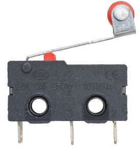
The Limit Switch KW12-3 is a compact and reliable mechanical switch designed to detect the presence or position of an object. It is widely used in industrial automation systems, machinery, and safety applications. The switch operates by physically interacting with a moving object, triggering its internal mechanism to open or close an electrical circuit. Its robust design and versatility make it suitable for a variety of environments, including manufacturing lines, robotics, and home automation projects.
Explore Projects Built with Limit Switch KW12-3


Explore Projects Built with Limit Switch KW12-3
Common Applications and Use Cases
- Detecting the position of moving parts in machinery
- Safety interlocks in industrial equipment
- End-stop detection in 3D printers and CNC machines
- Robotics for object detection and control
- Home automation systems for door or window position sensing
Technical Specifications
The KW12-3 limit switch is designed for low-voltage and low-current applications, making it ideal for control circuits. Below are its key technical details:
Key Technical Details
- Operating Voltage: 125V AC / 250V AC
- Rated Current: 5A
- Contact Configuration: SPDT (Single Pole Double Throw)
- Mechanical Life: 1,000,000 cycles
- Electrical Life: 50,000 cycles
- Operating Force: 50gf to 200gf
- Operating Temperature: -25°C to +85°C
- Mounting Style: Screw or PCB mount
- Dimensions: 27.8mm x 10.3mm x 15.9mm (L x W x H)
Pin Configuration and Descriptions
The KW12-3 has three terminals, corresponding to its SPDT configuration. The table below describes each terminal:
| Pin Name | Description |
|---|---|
| COM | Common terminal. This is the main input terminal for the switch. |
| NO | Normally Open terminal. This terminal is connected to COM when the switch |
| is actuated (pressed). | |
| NC | Normally Closed terminal. This terminal is connected to COM when the switch |
| is not actuated (released). |
Usage Instructions
How to Use the KW12-3 in a Circuit
Wiring the Switch:
- Connect the COM terminal to the input voltage or signal source.
- Use the NO terminal if you want the circuit to close when the switch is pressed.
- Use the NC terminal if you want the circuit to open when the switch is pressed.
Mounting:
- Secure the switch using screws or integrate it into a PCB design.
- Ensure the actuator lever is positioned to interact with the moving object.
Testing:
- Use a multimeter to verify the continuity between terminals (COM-NO and COM-NC) when the switch is actuated and released.
Important Considerations and Best Practices
- Avoid exceeding the rated voltage and current to prevent damage to the switch.
- Ensure proper alignment of the actuator lever with the moving object for reliable operation.
- Use debounce circuitry or software to handle mechanical bounce when interfacing with microcontrollers.
- Protect the switch from excessive force or environmental factors like dust and moisture.
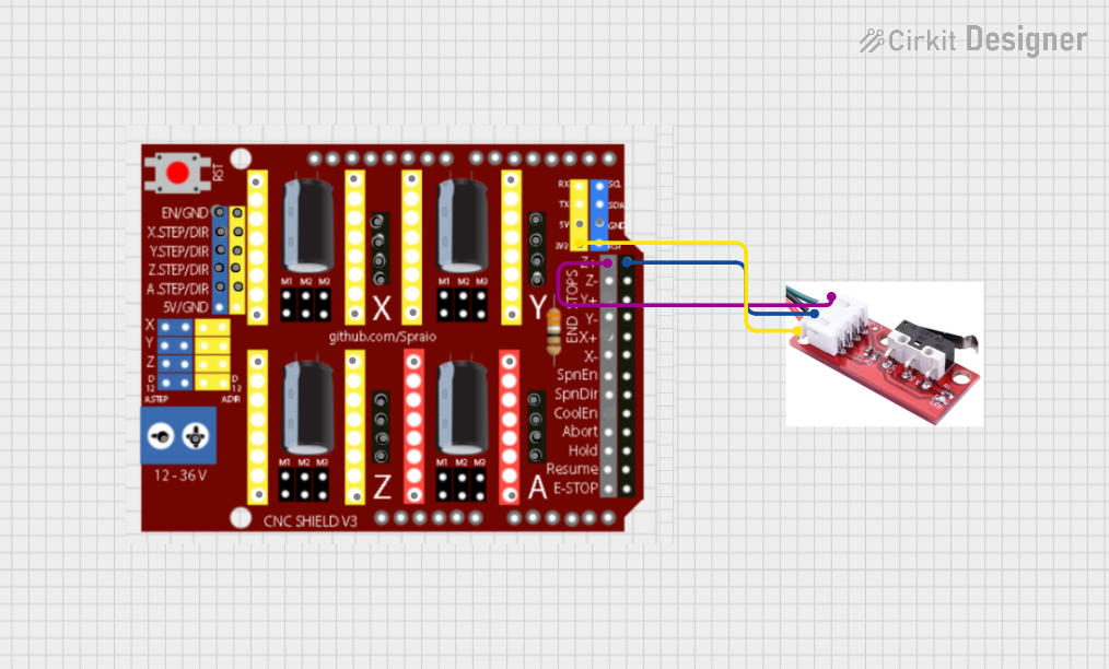
Example: Connecting to an Arduino UNO
The KW12-3 can be used with an Arduino UNO for position detection. Below is an example circuit and code:
Circuit
- Connect the COM terminal to the Arduino's GND pin.
- Connect the NO terminal to a digital input pin (e.g., D2) on the Arduino.
- Use a pull-up resistor (10kΩ) between the digital input pin and 5V to ensure a stable signal.
Code
// Example code for using the KW12-3 limit switch with Arduino UNO
const int switchPin = 2;  // Pin connected to the NO terminal of the switch
const int ledPin = 13;    // Built-in LED pin for status indication

void setup() {
  pinMode(switchPin, INPUT_PULLUP); // Set switch pin as input with internal pull-up
  pinMode(ledPin, OUTPUT);          // Set LED pin as output
  Serial.begin(9600);               // Initialize serial communication
}

void loop() {
  int switchState = digitalRead(switchPin); // Read the state of the switch

  if (switchState == LOW) { // Switch is pressed (NO connected to COM)
    digitalWrite(ledPin, HIGH); // Turn on the LED
    Serial.println("Switch Pressed");
  } else { // Switch is not pressed (NO disconnected from COM)
    digitalWrite(ledPin, LOW);  // Turn off the LED
    Serial.println("Switch Released");
  }

  delay(100); // Small delay to avoid rapid state changes
}
Troubleshooting and FAQs
Common Issues and Solutions
Switch Not Responding:
- Cause: Loose or incorrect wiring.
- Solution: Verify all connections and ensure the switch terminals are properly wired.
Inconsistent Behavior:
- Cause: Mechanical bounce or poor alignment of the actuator.
- Solution: Use debounce circuitry or software, and check the alignment of the actuator.
Switch Fails to Actuate:
- Cause: Excessive force or environmental damage.
- Solution: Inspect the switch for physical damage and replace if necessary.
Arduino Not Detecting the Switch:
- Cause: Missing pull-up resistor or incorrect pin configuration.
- Solution: Ensure a pull-up resistor is used and verify the Arduino pin setup.
FAQs
Q1: Can the KW12-3 handle high-current loads?
A1: No, the KW12-3 is rated for a maximum current of 5A. For higher loads, use a relay or contactor.
Q2: Is the KW12-3 waterproof?
A2: No, the KW12-3 is not waterproof. Use a protective enclosure if operating in wet environments.
Q3: Can I use the KW12-3 with a Raspberry Pi?
A3: Yes, the KW12-3 can be used with a Raspberry Pi. Connect it to a GPIO pin and use a pull-up or pull-down resistor as needed.
Q4: How do I prevent false triggering due to vibration?
A4: Use debounce circuitry or software to filter out noise caused by vibrations.