
How to Use Potentiometer: Examples, Pinouts, and Specs
 Design with Potentiometer in Cirkit Designer
Introduction
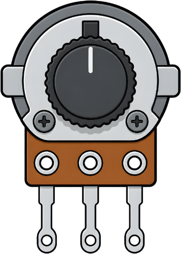
The Potentiometer by LI Blocks is a variable resistor designed to adjust voltage levels in a circuit. By varying its resistance, it allows for precise control of current flow and signal levels. This component is widely used in applications requiring adjustable parameters, such as volume control, brightness adjustment, and sensor calibration.
Explore Projects Built with Potentiometer
 Open Project in Cirkit Designer
 Open Project in Cirkit Designer
 Open Project in Cirkit Designer
 Open Project in Cirkit Designer
Explore Projects Built with Potentiometer
Open Project in Cirkit DesignerOpen Project in Cirkit DesignerOpen Project in Cirkit DesignerOpen Project in Cirkit DesignerCommon Applications
- Audio equipment (e.g., volume knobs)
- Light dimmers
- Adjustable power supplies
- Sensor calibration in microcontroller projects
- Voltage dividers in analog circuits
Technical Specifications
Below are the key technical details for the LI Blocks Potentiometer:
| Parameter | Value |
|---|---|
| Resistance Range | 1 kΩ to 1 MΩ (varies by model) |
| Tolerance | ±10% |
| Power Rating | 0.25 W (typical) |
| Operating Voltage | 0–50 V DC |
| Operating Temperature | -40°C to +85°C |
| Adjustment Type | Rotary or linear |
| Shaft Length | 15 mm |
| Mounting Type | Through-hole or panel mount |
Pin Configuration
The potentiometer typically has three pins, as described below:
| Pin | Name | Description |
|---|---|---|
| 1 | Terminal 1 | One end of the resistive track. Connect to the voltage source or ground. |
| 2 | Wiper | The adjustable middle pin. Outputs the variable voltage based on the knob's position. |
| 3 | Terminal 2 | The other end of the resistive track. Connect to ground or the voltage source. |
Usage Instructions
How to Use the Potentiometer in a Circuit
Basic Voltage Divider Setup:
- Connect Terminal 1 to the positive voltage source.
- Connect Terminal 2 to ground.
- The Wiper (Pin 2) will output a variable voltage depending on the knob's position.
Adjusting Resistance:
- Rotate the knob clockwise to increase resistance between the wiper and Terminal 2.
- Rotate the knob counterclockwise to decrease resistance.
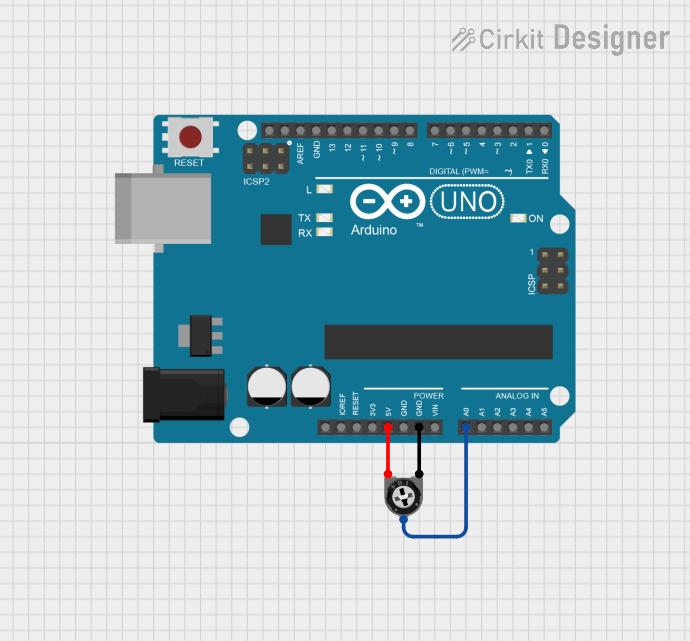
Connecting to an Arduino UNO:
- Use the potentiometer as an analog input to control parameters like LED brightness or motor speed.
- Connect Terminal 1 to 5V, Terminal 2 to GND, and the Wiper to an analog input pin (e.g., A0).
Example Code for Arduino UNO
The following code demonstrates how to read the potentiometer's value and control an LED's brightness:
// Define pin connections
const int potPin = A0;  // Potentiometer wiper connected to analog pin A0
const int ledPin = 9;   // LED connected to digital pin 9 (PWM-enabled)

void setup() {
  pinMode(ledPin, OUTPUT);  // Set LED pin as output
  Serial.begin(9600);       // Initialize serial communication for debugging
}

void loop() {
  int potValue = analogRead(potPin);  // Read potentiometer value (0-1023)
  int ledBrightness = map(potValue, 0, 1023, 0, 255);  // Map to PWM range (0-255)

  analogWrite(ledPin, ledBrightness);  // Set LED brightness
  Serial.print("Potentiometer Value: ");  // Print the potentiometer value
  Serial.println(potValue);              // to the Serial Monitor

  delay(10);  // Small delay for stability
}
Best Practices
- Avoid applying voltages beyond the specified operating range to prevent damage.
- Use a multimeter to verify resistance values before connecting to sensitive circuits.
- For panel-mounted potentiometers, ensure the shaft is securely fastened to avoid mechanical wear.
Troubleshooting and FAQs
Common Issues
No Output Voltage:
- Ensure the potentiometer is properly connected to the circuit.
- Verify that the voltage source is functioning correctly.
Inconsistent or Noisy Output:
- Dust or debris inside the potentiometer may cause erratic behavior. Clean the component using compressed air or contact cleaner.
- Check for loose connections or damaged solder joints.
Potentiometer Not Adjusting Properly:
- Confirm that the potentiometer's resistance range matches your circuit requirements.
- Inspect the shaft for mechanical damage or wear.
FAQs
Q: Can I use the potentiometer to control AC voltage?
A: No, this potentiometer is designed for DC circuits only. Using it with AC voltage may damage the component.
Q: How do I know which pin is the wiper?
A: The wiper is typically the middle pin. You can confirm this by measuring resistance with a multimeter while adjusting the knob.
Q: What happens if I reverse the connections on Terminal 1 and Terminal 2?
A: The potentiometer will still function, but the direction of adjustment (clockwise vs. counterclockwise) will be reversed.
By following this documentation, you can effectively integrate the LI Blocks Potentiometer into your projects for precise voltage and resistance control.