How to Use 12V DC LED Car Engine Start Stop Push Button: Examples, Pinouts, and Specs

Introduction
The 12V DC LED Car Engine Start Stop Push Button (Manufacturer: Keenso, Part ID: Keensoq1bn5fs2iz-01) is a robust and reliable push button switch designed for automotive applications. This component allows users to start or stop a vehicle's engine with a single press. It features an integrated LED indicator that provides visual feedback, enhancing usability and aesthetics. The button is designed to operate at 12V DC, making it compatible with most automotive electrical systems.
Explore Projects Built with 12V DC LED Car Engine Start Stop Push Button
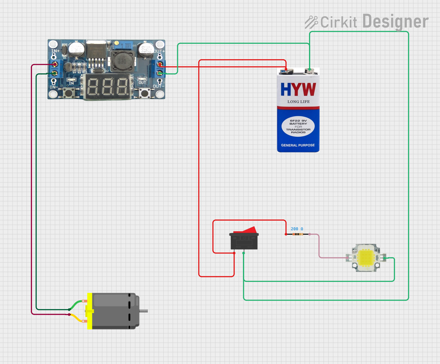
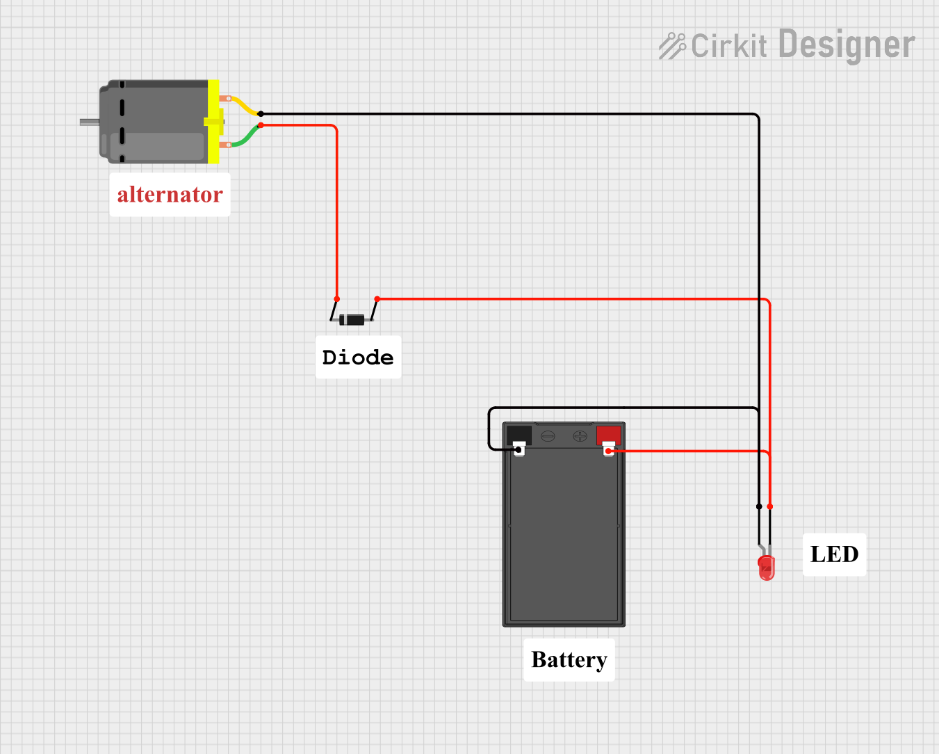
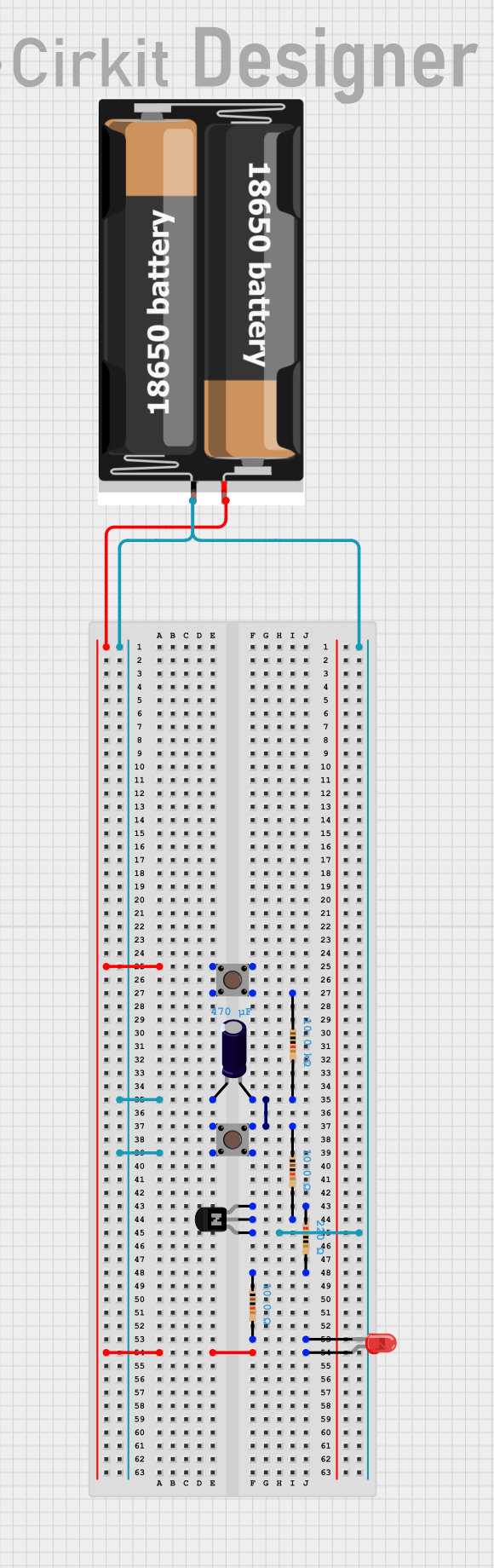

Explore Projects Built with 12V DC LED Car Engine Start Stop Push Button
Common Applications and Use Cases
- Automotive engine start/stop systems
- Custom car modifications and upgrades
- Replacement for traditional ignition switches
- DIY automotive projects
- Applications requiring a durable push button with LED feedback
Technical Specifications
Below are the key technical details and pin configuration for the Keensoq1bn5fs2iz-01:
Key Technical Details
| Parameter | Specification |
|---|---|
| Operating Voltage | 12V DC |
| Current Rating | ≤ 3A |
| LED Indicator Color | Red |
| Button Type | Momentary Push Button |
| Material | Metal Alloy (Housing), Plastic (Base) |
| Mounting Hole Diameter | 22mm |
| Operating Temperature | -20°C to 85°C |
| Waterproof Rating | IP65 |
Pin Configuration and Descriptions
The push button has four terminals, as described in the table below:
| Pin Number | Label | Description |
|---|---|---|
| 1 | LED+ | Positive terminal for the LED indicator (12V DC) |
| 2 | LED- | Negative terminal for the LED indicator (GND) |
| 3 | NO (Normally Open) | Connects to the circuit when the button is pressed |
| 4 | COM (Common) | Common terminal for the switch circuit |
Usage Instructions
How to Use the Component in a Circuit
- Mounting the Button: Drill a 22mm hole in the desired panel or dashboard. Insert the button and secure it using the provided nut.
- Wiring the LED Indicator:
- Connect the LED+ pin to a 12V DC power source.
- Connect the LED- pin to the ground (GND).
- Wiring the Switch:
- Connect the COM pin to the power source or control circuit.
- Connect the NO pin to the load or the circuit you want to control.
- Testing:
- Press the button to ensure the LED lights up and the circuit is activated.
- Release the button to confirm the circuit is deactivated.
Important Considerations and Best Practices
- Ensure the operating voltage does not exceed 12V DC to avoid damaging the component.
- Use appropriate wire gauges to handle the current (≤ 3A) safely.
- If used in a vehicle, ensure proper grounding to avoid electrical noise or interference.
- For waterproofing, ensure the button is securely mounted and the connections are insulated.
Example: Connecting to an Arduino UNO
The push button can be used with an Arduino UNO for custom control applications. Below is an example of wiring and code:
Wiring
- Connect COM to a digital input pin on the Arduino (e.g., D2).
- Connect NO to the ground (GND) through a pull-down resistor (10kΩ).
- Connect LED+ to the 5V pin on the Arduino (use a 220Ω resistor in series).
- Connect LED- to the ground (GND).
Arduino Code
// Define pin numbers
const int buttonPin = 2;  // Pin connected to the button's COM terminal
const int ledPin = 13;    // Built-in LED on Arduino for feedback

void setup() {
  pinMode(buttonPin, INPUT);  // Set button pin as input
  pinMode(ledPin, OUTPUT);    // Set LED pin as output
  digitalWrite(ledPin, LOW);  // Ensure LED is off initially
}

void loop() {
  int buttonState = digitalRead(buttonPin);  // Read the button state

  if (buttonState == HIGH) {
    // If button is pressed, turn on the LED
    digitalWrite(ledPin, HIGH);
  } else {
    // If button is not pressed, turn off the LED
    digitalWrite(ledPin, LOW);
  }
}
Troubleshooting and FAQs
Common Issues and Solutions
| Issue | Possible Cause | Solution |
|---|---|---|
| LED does not light up | Incorrect wiring or no power to LED pins | Verify connections to LED+ and LED- |
| Button does not activate the circuit | Miswiring of COM and NO pins | Check and correct the wiring |
| Button feels loose after mounting | Improper installation | Ensure the nut is tightened securely |
| LED flickers during operation | Electrical noise or unstable power supply | Use a capacitor across the power supply |
FAQs
Can this button be used with a 24V system?
No, this button is designed for 12V DC systems only. Using it with higher voltages may damage the component.Is the button waterproof?
Yes, the button has an IP65 rating, making it resistant to water splashes and dust. However, it is not suitable for full submersion.Can the LED indicator color be changed?
No, the LED is built-in and fixed to red.What is the lifespan of the button?
The button is rated for over 50,000 press cycles under normal operating conditions.
By following this documentation, users can effectively integrate the 12V DC LED Car Engine Start Stop Push Button into their automotive or DIY projects.