How to Use xcluma MCP4725 I2C DAC Breakout module: Examples, Pinouts, and Specs
Introduction
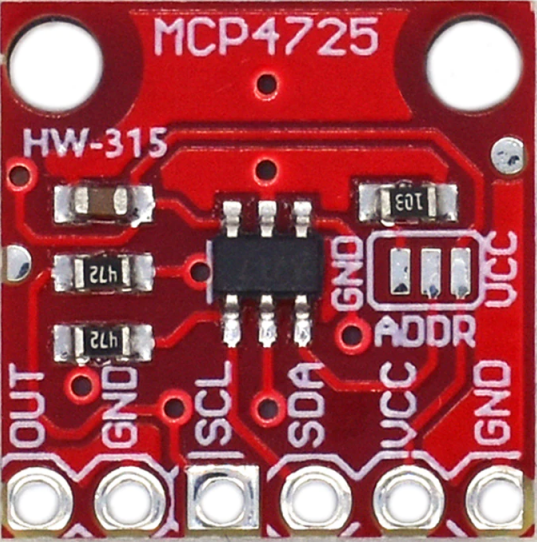
The xcluma MCP4725 I2C DAC Breakout module is a compact and efficient digital-to-analog converter (DAC) that provides a precise voltage output, typically used for fine-tuning analog signals in various electronic applications. This module is based on the MCP4725 chip from Microchip Technology and communicates via the I2C interface, making it an excellent choice for projects that require a simple and reliable method to produce an analog output from a digital source.
Explore Projects Built with xcluma MCP4725 I2C DAC Breakout module
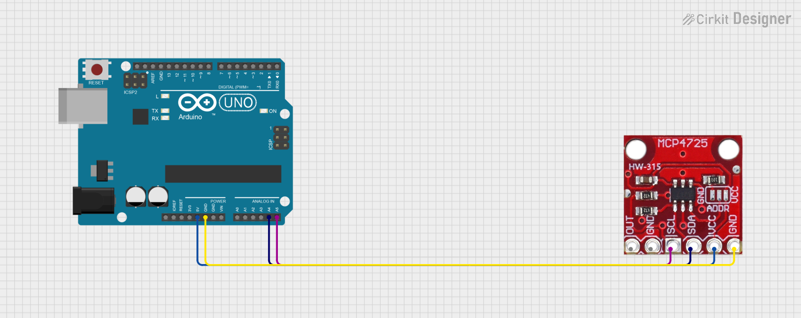

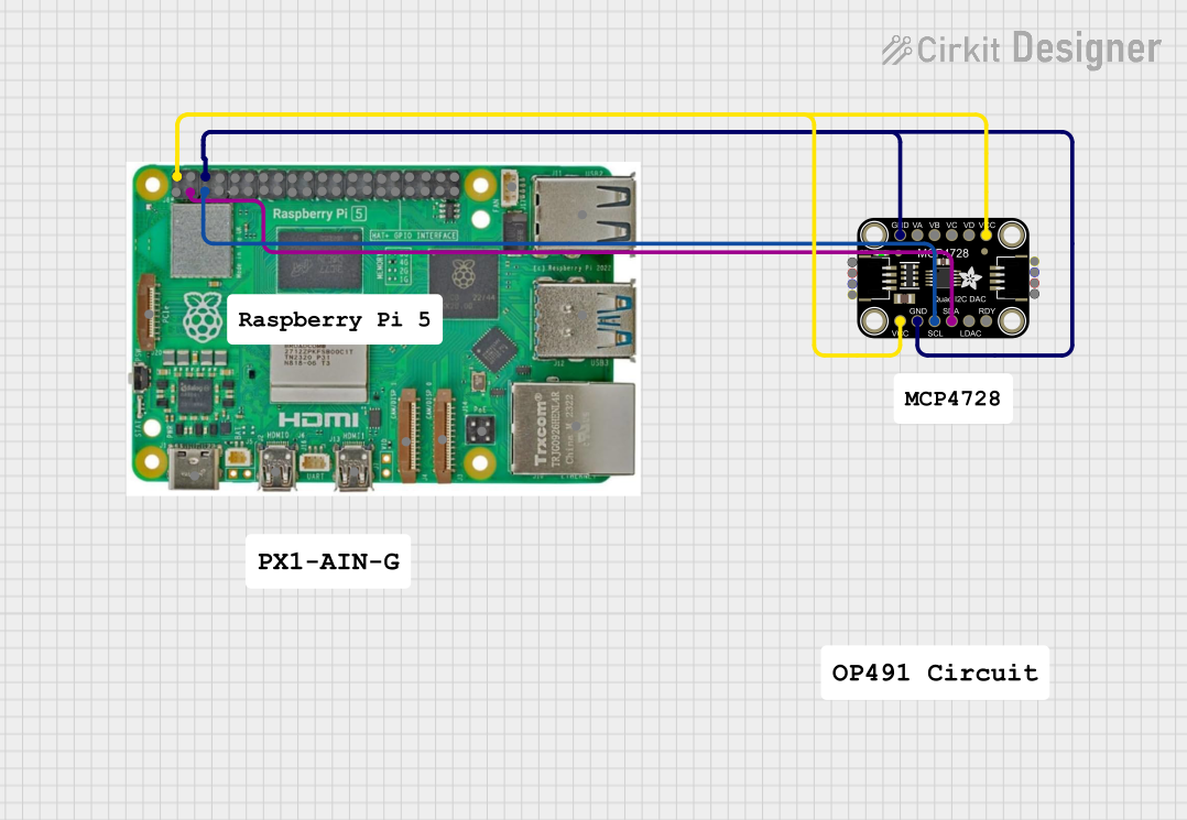
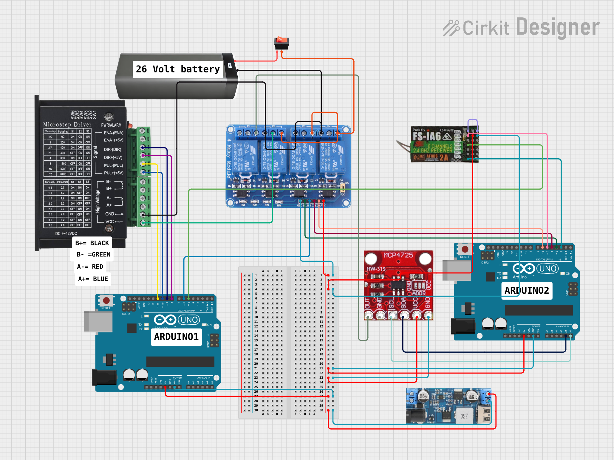
Explore Projects Built with xcluma MCP4725 I2C DAC Breakout module
Common Applications and Use Cases
- Generating precise analog control voltages for dimming LEDs or controlling motor speeds.
- Creating audio signals for music instruments or sound generation.
- Simulating sensor outputs for testing and development purposes.
- Providing a variable voltage reference for analog circuits.
Technical Specifications
Key Technical Details
- Resolution: 12-bit
- Interface: I2C
- Supply Voltage (VDD): 2.7V to 5.5V
- Output Voltage Range: 0V to VDD
- Maximum Output Current: 25 mA
- Settling Time: Typically 6 µs
- I2C Address: 0x60 (default, configurable with solder jumpers)
Pin Configuration and Descriptions
| Pin | Description |
|---|---|
| VDD | Power supply (2.7V to 5.5V) |
| GND | Ground connection |
| SDA | I2C Data line |
| SCL | I2C Clock line |
| VOUT | Analog voltage output |
| A0 | Address select bit 0 (optional, for changing I2C address) |
Usage Instructions
How to Use the Component in a Circuit
- Powering the Module: Connect the VDD pin to a 2.7V to 5.5V power supply and the GND pin to the ground.
- Connecting to I2C: Attach the SDA and SCL pins to the corresponding I2C data and clock lines on your microcontroller.
- Output Voltage: Connect the VOUT pin to the input of the device you wish to control with the analog voltage.
Important Considerations and Best Practices
- Ensure that the power supply does not exceed the maximum voltage rating of 5.5V.
- Use pull-up resistors on the I2C data and clock lines if they are not already present on the microcontroller board.
- Avoid running high-current loads directly from the VOUT pin; use an amplifier or buffer if necessary.
- To prevent noise, keep the analog signal paths as short as possible and away from high-frequency digital traces.
Example Code for Arduino UNO
#include <Wire.h>
#include <Adafruit_MCP4725.h>

Adafruit_MCP4725 dac;

void setup() {
  Wire.begin();        // Join I2C bus
  dac.begin(0x60);     // Initialize MCP4725, default address 0x60
}

void loop() {
  uint16_t outputVoltage;

  // Generate a sawtooth wave
  for (outputVoltage = 0; outputVoltage < 4096; outputVoltage++) {
    dac.setVoltage(outputVoltage, false);
    delay(1);
  }
}
Troubleshooting and FAQs
Common Issues Users Might Face
- No Output Voltage: Ensure that the module is powered correctly and that the I2C lines are properly connected.
- Inaccurate Output Voltage: Check if the power supply is stable and within the specified range.
- I2C Communication Failure: Verify that the correct I2C address is being used and that there are pull-up resistors on the SDA and SCL lines.
Solutions and Tips for Troubleshooting
- If the output voltage is not as expected, recalibrate the DAC or check for any potential interference on the I2C lines.
- For I2C communication issues, use a logic analyzer or oscilloscope to inspect the SDA and SCL signals for proper operation.
- Ensure that the microcontroller's I2C library supports the clock frequency used by the MCP4725.
FAQs
Q: Can I change the I2C address of the module? A: Yes, the A0 pin can be used to configure the least significant bit of the I2C address.
Q: What is the maximum resolution of the DAC? A: The MCP4725 provides a 12-bit resolution, allowing for 4096 different voltage levels.
Q: How do I connect multiple MCP4725 modules to the same I2C bus? A: You can connect multiple modules by configuring each with a unique I2C address using the A0 pin.
Q: Is it possible to store the desired voltage output after power-off? A: Yes, the MCP4725 has an EEPROM that can be used to store the voltage output settings across power cycles.