Cirkit Designer Logo
Cirkit Designer
Your all-in-one circuit design IDE
Home / 
Component Documentation

How to Use Laser Diode Module: Examples, Pinouts, and Specs

Image of Laser Diode Module
Cirkit Designer LogoDesign with Laser Diode Module in Cirkit Designer

Introduction

A Laser Diode Module is a compact device that emits coherent light through the process of stimulated emission. It is widely used in applications requiring precise and focused light beams. Common use cases include:

  • Optical Communication: Used in fiber-optic systems for high-speed data transmission.
  • Laser Printing: Provides the light source for precise imaging in printers.
  • Medical Devices: Utilized in surgical tools and diagnostic equipment.
  • Measurement and Sensing: Employed in distance measurement, barcode scanning, and alignment tools.
  • DIY Electronics Projects: Popular in hobbyist projects for creating laser pointers or light-based communication systems.

Explore Projects Built with Laser Diode Module

Use Cirkit Designer to design, explore, and prototype these projects online. Some projects support real-time simulation. Click "Open Project" to start designing instantly!
Battery-Powered Laser Emitter with Solar Charging and LED Indicator
Image of rx: A project utilizing Laser Diode Module in a practical application
This circuit is a solar-powered laser emitter system with an LED indicator. The solar panel charges a 18650 battery via a TP4056 charging module, and a push button controls the activation of the laser emitter and the LED through a MOSFET switch.
Cirkit Designer LogoOpen Project in Cirkit Designer
Arduino-Controlled Laser Security System with LDR and Buzzer
Image of LASER SECURITY SYSTEM: A project utilizing Laser Diode Module in a practical application
This circuit features an Arduino UNO interfaced with an LDR module, a laser diode, and a buzzer. The Arduino is programmed to react to light levels detected by the LDR, potentially activating the buzzer or laser diode. The circuit is powered by a 9V battery, with the Arduino regulating power to the laser diode and monitoring the LDR output.
Cirkit Designer LogoOpen Project in Cirkit Designer
Arduino-Controlled Laser Security System with LDR and Buzzer
Image of home security system: A project utilizing Laser Diode Module in a practical application
This circuit features an LDR (Light Dependent Resistor) connected to an Arduino UNO for light sensing, a KY-008 Laser Emitter module controlled by the Arduino via digital pin D2, and a buzzer connected to digital pin D9. The LDR and the laser emitter are powered by the Arduino's 5V output, and all components share a common ground. The provided code skeleton suggests that the Arduino is intended to perform actions based on the LDR readings and control the laser and buzzer, but the specific functionality is not implemented in the given code.
Cirkit Designer LogoOpen Project in Cirkit Designer
Arduino UNO Laser Tripwire Security System with GSM Alert
Image of Laser home security system: A project utilizing Laser Diode Module in a practical application
This circuit is a laser tripwire security system using an Arduino UNO. When the laser beam is interrupted, the system triggers a buzzer, lights up an LED, and sends an alert via a SIM800L GSM module. The system also includes an LDR module to detect the laser beam and two LEDs to indicate the system status.
Cirkit Designer LogoOpen Project in Cirkit Designer

Explore Projects Built with Laser Diode Module

Use Cirkit Designer to design, explore, and prototype these projects online. Some projects support real-time simulation. Click "Open Project" to start designing instantly!
Image of rx: A project utilizing Laser Diode Module in a practical application
Battery-Powered Laser Emitter with Solar Charging and LED Indicator
This circuit is a solar-powered laser emitter system with an LED indicator. The solar panel charges a 18650 battery via a TP4056 charging module, and a push button controls the activation of the laser emitter and the LED through a MOSFET switch.
Cirkit Designer LogoOpen Project in Cirkit Designer
Image of LASER SECURITY SYSTEM: A project utilizing Laser Diode Module in a practical application
Arduino-Controlled Laser Security System with LDR and Buzzer
This circuit features an Arduino UNO interfaced with an LDR module, a laser diode, and a buzzer. The Arduino is programmed to react to light levels detected by the LDR, potentially activating the buzzer or laser diode. The circuit is powered by a 9V battery, with the Arduino regulating power to the laser diode and monitoring the LDR output.
Cirkit Designer LogoOpen Project in Cirkit Designer
Image of home security system: A project utilizing Laser Diode Module in a practical application
Arduino-Controlled Laser Security System with LDR and Buzzer
This circuit features an LDR (Light Dependent Resistor) connected to an Arduino UNO for light sensing, a KY-008 Laser Emitter module controlled by the Arduino via digital pin D2, and a buzzer connected to digital pin D9. The LDR and the laser emitter are powered by the Arduino's 5V output, and all components share a common ground. The provided code skeleton suggests that the Arduino is intended to perform actions based on the LDR readings and control the laser and buzzer, but the specific functionality is not implemented in the given code.
Cirkit Designer LogoOpen Project in Cirkit Designer
Image of Laser home security system: A project utilizing Laser Diode Module in a practical application
Arduino UNO Laser Tripwire Security System with GSM Alert
This circuit is a laser tripwire security system using an Arduino UNO. When the laser beam is interrupted, the system triggers a buzzer, lights up an LED, and sends an alert via a SIM800L GSM module. The system also includes an LDR module to detect the laser beam and two LEDs to indicate the system status.
Cirkit Designer LogoOpen Project in Cirkit Designer

Technical Specifications

Below are the key technical details of a typical Laser Diode Module:

Parameter Value
Operating Voltage 3V to 5V DC
Operating Current 20mA to 40mA
Wavelength 650nm (Red Laser)
Output Power <5mW
Beam Divergence <1.2 mrad
Operating Temperature -10°C to 50°C
Dimensions 6mm (diameter) x 18mm (length)

Pin Configuration and Descriptions

The Laser Diode Module typically has three pins or wires for connection:

Pin/Wire Description
VCC (Red) Positive power supply (3V to 5V DC)
GND (Black) Ground connection
TTL (Yellow) Optional control pin for modulation (PWM)

Note: Some modules may only have two wires (VCC and GND) without TTL functionality.

Usage Instructions

How to Use the Laser Diode Module in a Circuit

  1. Power Supply: Connect the red wire (VCC) to a 3V-5V DC power source and the black wire (GND) to ground.
  2. Optional Modulation: If the module has a TTL pin, connect it to a PWM-capable pin on a microcontroller (e.g., Arduino) to control the laser's on/off state or intensity.
  3. Mounting: Secure the module in a stable position to ensure the laser beam remains focused and aligned.
  4. Safety Precautions: Always avoid direct eye exposure to the laser beam. Use appropriate safety goggles if necessary.

Important Considerations and Best Practices

  • Current Limiting: Ensure the current supplied to the module does not exceed its rated value to prevent damage.
  • Heat Dissipation: Avoid prolonged operation at high power to prevent overheating.
  • Polarity: Double-check the polarity of the connections to avoid damaging the module.
  • Environmental Conditions: Operate the module within the specified temperature range for optimal performance.

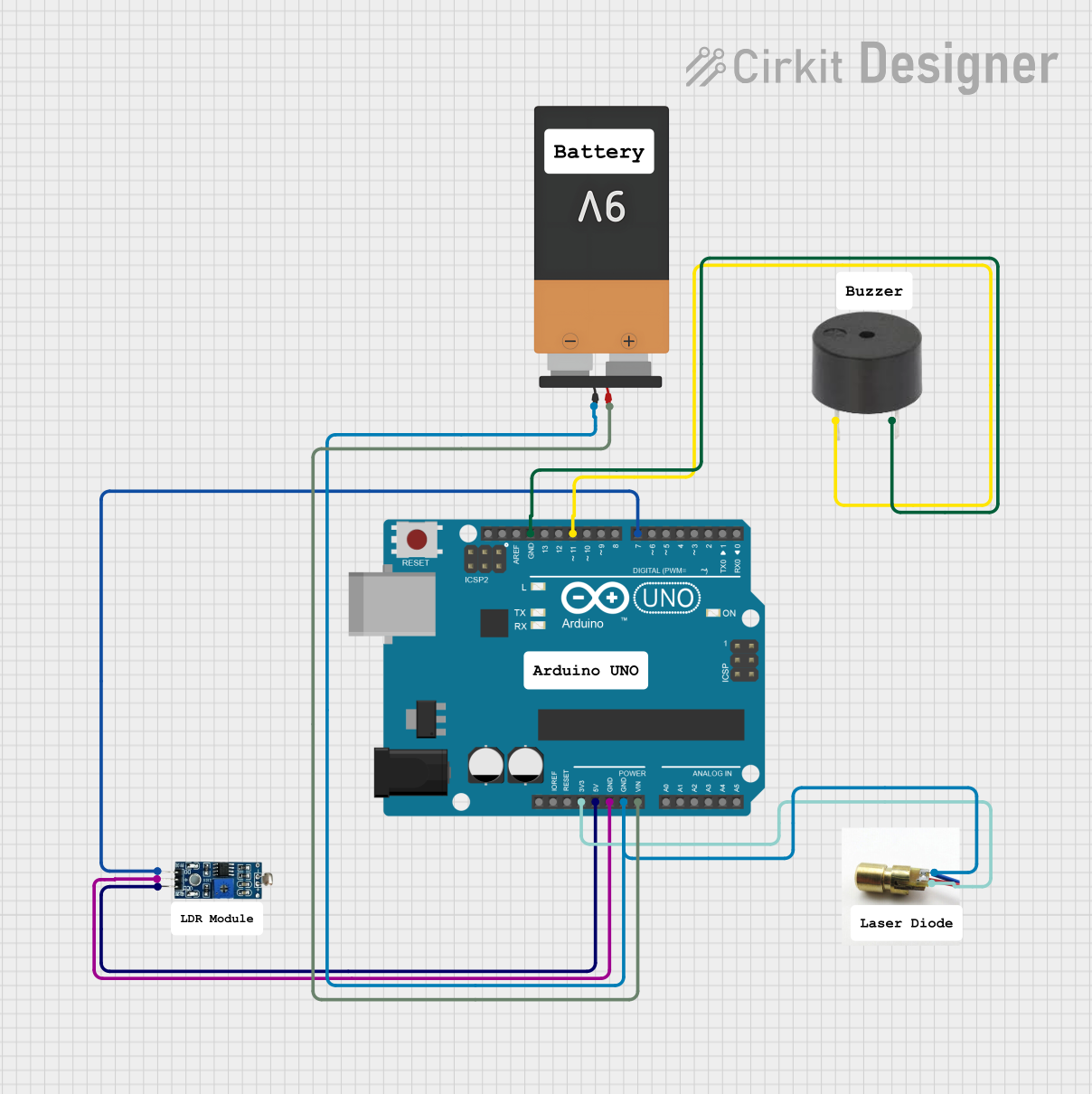
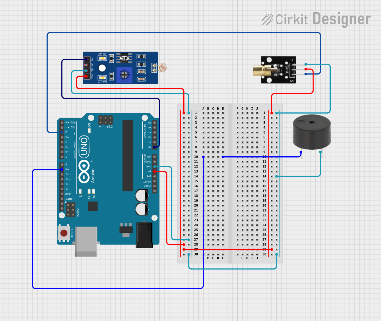
Example: Connecting to an Arduino UNO

Below is an example of how to connect and control a Laser Diode Module using an Arduino UNO:

Circuit Connections

  • Connect the VCC (Red) wire of the module to the 5V pin on the Arduino.
  • Connect the GND (Black) wire of the module to the GND pin on the Arduino.
  • If the module has a TTL (Yellow) wire, connect it to Pin 9 on the Arduino for PWM control.

Arduino Code

// Laser Diode Module Control with Arduino UNO
// Connect the TTL pin of the Laser Diode Module to Pin 9 on the Arduino.
// Ensure the module's VCC and GND are connected to the Arduino's 5V and GND.

const int laserPin = 9; // Define the pin connected to the TTL input of the laser

void setup() {
  pinMode(laserPin, OUTPUT); // Set the laser pin as an output
}

void loop() {
  digitalWrite(laserPin, HIGH); // Turn the laser ON
  delay(1000);                  // Keep the laser ON for 1 second
  digitalWrite(laserPin, LOW);  // Turn the laser OFF
  delay(1000);                  // Keep the laser OFF for 1 second
}

Tip: Use analogWrite(laserPin, value) (where value is between 0 and 255) to control the laser's brightness if the module supports PWM.

Troubleshooting and FAQs

Common Issues and Solutions

  1. Laser Does Not Turn On:

    • Cause: Incorrect wiring or insufficient power supply.
    • Solution: Verify the connections and ensure the power supply provides 3V-5V DC.
  2. Laser Beam is Weak or Flickering:

    • Cause: Insufficient current or loose connections.
    • Solution: Check the power source and ensure all connections are secure.
  3. Module Overheats:

    • Cause: Prolonged operation or excessive current.
    • Solution: Limit the operating time and ensure the current does not exceed the rated value.
  4. TTL Control Not Working:

    • Cause: Incorrect PWM signal or damaged TTL pin.
    • Solution: Verify the PWM signal from the microcontroller and check the module's datasheet for compatibility.

FAQs

  • Q: Can I power the Laser Diode Module with a 9V battery?
    A: No, the module is designed for 3V-5V DC. Using a 9V battery without a voltage regulator may damage the module.

  • Q: Is the Laser Diode Module safe for DIY projects?
    A: Yes, but always follow safety precautions to avoid direct eye exposure to the laser beam.

  • Q: Can I use the module without the TTL pin?
    A: Yes, the module will operate continuously when powered if the TTL pin is not used.

  • Q: How do I focus the laser beam?
    A: Some modules have an adjustable lens for focusing. Rotate the lens gently to adjust the beam.

By following this documentation, you can safely and effectively use a Laser Diode Module in your projects.