
How to Use SparkFun AD5330 8-Bit Parallel DAC Breakout v1.1: Examples, Pinouts, and Specs
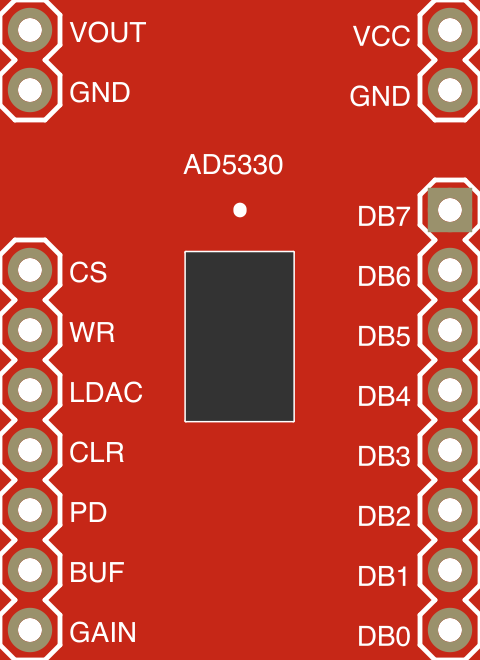
 Design with SparkFun AD5330 8-Bit Parallel DAC Breakout v1.1 in Cirkit Designer
Introduction
The SparkFun AD5330 is an 8-bit Digital-to-Analog Converter (DAC) designed to convert digital signals into precise analog outputs. This breakout board simplifies the process of interfacing with the AD5330 IC by providing easy access to its pins and features. It is ideal for applications requiring smooth and accurate analog signal generation, such as audio processing, waveform generation, and control systems.
Explore Projects Built with SparkFun AD5330 8-Bit Parallel DAC Breakout v1.1
 Open Project in Cirkit Designer
 Open Project in Cirkit Designer
 Open Project in Cirkit Designer
 Open Project in Cirkit Designer
Explore Projects Built with SparkFun AD5330 8-Bit Parallel DAC Breakout v1.1
Open Project in Cirkit DesignerOpen Project in Cirkit DesignerOpen Project in Cirkit DesignerOpen Project in Cirkit DesignerCommon Applications
- Audio signal generation and processing
- Waveform generation for testing and measurement
- Analog control in robotics and automation
- Signal conditioning in embedded systems
- Educational projects involving DACs and analog electronics
Technical Specifications
The SparkFun AD5330 breakout board is built around the Analog Devices AD5330 DAC IC. Below are the key technical details:
Key Specifications
| Parameter | Value |
|---|---|
| Resolution | 8 bits |
| Output Voltage Range | 0V to VREF (typically 0V to 2.5V) |
| Reference Voltage (VREF) | 2.5V (external or internal reference) |
| Supply Voltage (VDD) | 2.5V to 5.5V |
| Interface Type | 8-bit parallel |
| Maximum Update Rate | 167 kSPS |
| Power Consumption | Low power (typical 0.7 mW at 3V supply) |
| Operating Temperature | -40°C to +105°C |
Pin Configuration
The breakout board provides access to the AD5330's pins via labeled headers. Below is the pin configuration:
| Pin Name | Pin Type | Description |
|---|---|---|
| D0-D7 | Digital Input | 8-bit parallel data input for the DAC. D0 is the least significant bit (LSB). |
| WR | Digital Input | Write strobe. Active low. Triggers data transfer to the DAC. |
| CS | Digital Input | Chip select. Active low. Enables communication with the DAC. |
| LDAC | Digital Input | Load DAC. Active low. Updates the DAC output when asserted. |
| VDD | Power | Positive supply voltage (2.5V to 5.5V). |
| GND | Power | Ground connection. |
| VREF | Analog Input | Reference voltage input for setting the DAC output range. |
| VOUT | Analog Output | Analog output voltage corresponding to the digital input. |
Usage Instructions
How to Use the Component in a Circuit
- Power Supply: Connect the VDD pin to a stable power source (2.5V to 5.5V) and the GND pin to ground.
- Reference Voltage: Provide a reference voltage (VREF) to set the output range. For example, use 2.5V for a 0V to 2.5V output range.
- Digital Inputs: Connect the 8-bit digital input pins (D0-D7) to a microcontroller or other digital source.
- Control Signals:
- Use the
CSpin to enable communication with the DAC. - Use the
WRpin to latch the digital data into the DAC. - Use the
LDACpin to update the analog output.
- Use the
- Analog Output: The DAC output voltage is available on the
VOUTpin. This voltage corresponds to the digital input value scaled by the reference voltage.
Important Considerations
- Ensure that the reference voltage (VREF) is stable and within the specified range.
- Avoid exceeding the maximum voltage ratings for any pin to prevent damage.
- Use decoupling capacitors (e.g., 0.1 µF) near the power supply pins to reduce noise.
- For best performance, keep the digital and analog signal paths separate to minimize interference.
Example: Interfacing with Arduino UNO
Below is an example of how to interface the SparkFun AD5330 with an Arduino UNO to generate an analog output:
Circuit Connections
| AD5330 Pin | Arduino Pin | Description |
|---|---|---|
| D0-D7 | D2-D9 | Connect to Arduino digital pins 2 to 9. |
| WR | D10 | Write strobe control. |
| CS | D11 | Chip select control. |
| LDAC | D12 | Load DAC control. |
| VDD | 5V | Power supply from Arduino. |
| GND | GND | Ground connection. |
| VREF | 2.5V | External reference voltage. |
| VOUT | - | Connect to an oscilloscope or load. |
Arduino Code
// SparkFun AD5330 Example Code
// This code demonstrates how to send an 8-bit value to the AD5330 DAC
// using an Arduino UNO. The DAC output will generate a corresponding
// analog voltage.

#define WR_PIN 10  // Write strobe pin
#define CS_PIN 11  // Chip select pin
#define LDAC_PIN 12 // Load DAC pin

void setup() {
  // Set control pins as outputs
  pinMode(WR_PIN, OUTPUT);
  pinMode(CS_PIN, OUTPUT);
  pinMode(LDAC_PIN, OUTPUT);

  // Set initial states for control pins
  digitalWrite(WR_PIN, HIGH);
  digitalWrite(CS_PIN, HIGH);
  digitalWrite(LDAC_PIN, HIGH);

  // Set data pins (D0-D7) as outputs
  for (int i = 2; i <= 9; i++) {
    pinMode(i, OUTPUT);
  }
}

void loop() {
  // Example: Generate a ramp signal
  for (int value = 0; value < 256; value++) {
    sendToDAC(value);  // Send the value to the DAC
    delay(10);         // Delay for visualization
  }
}

void sendToDAC(byte value) {
  // Set data pins (D0-D7) to the desired value
  for (int i = 0; i < 8; i++) {
    digitalWrite(2 + i, (value >> i) & 0x01);
  }

  // Trigger the DAC to latch the data
  digitalWrite(CS_PIN, LOW);  // Enable the DAC
  digitalWrite(WR_PIN, LOW);  // Trigger write
  digitalWrite(WR_PIN, HIGH); // End write
  digitalWrite(CS_PIN, HIGH); // Disable the DAC

  // Update the DAC output
  digitalWrite(LDAC_PIN, LOW);  // Load the DAC
  digitalWrite(LDAC_PIN, HIGH); // End load
}
Troubleshooting and FAQs
Common Issues
No Output Voltage on VOUT:
- Ensure the DAC is powered correctly (VDD and GND connected).
- Verify that the reference voltage (VREF) is stable and within range.
- Check the digital input connections (D0-D7) and control signals (CS, WR, LDAC).
Incorrect Output Voltage:
- Confirm that the digital input value matches the expected output.
- Verify the reference voltage and ensure it is not fluctuating.
- Check for noise or interference in the circuit.
DAC Not Responding:
- Ensure the
CSandWRsignals are being toggled correctly. - Verify that the Arduino pins are configured as outputs.
- Ensure the
Tips for Troubleshooting
- Use an oscilloscope or logic analyzer to monitor the control signals (CS, WR, LDAC).
- Test the DAC with a fixed digital input value to verify the output voltage.
- Double-check all connections and ensure there are no loose wires.
FAQs
Q: Can I use a 3.3V microcontroller with the AD5330?
A: Yes, the AD5330 supports a supply voltage range of 2.5V to 5.5V, making it compatible with 3.3V systems.
Q: What happens if I don't connect the LDAC pin?
A: If the LDAC pin is not used, the DAC output will not update automatically. You can tie it to ground for continuous updates.
Q: Can I use the internal reference voltage of the AD5330?
A: No, the AD5330 does not have an internal reference. You must provide an external reference voltage to the VREF pin.