How to Use TB6612FNG Motor Driver: Examples, Pinouts, and Specs
Introduction
The TB6612FNG is a compact, efficient, and versatile dual motor driver capable of controlling two DC motors or one stepper motor. It is widely used in robotics, automation, and other motor control applications due to its built-in protection features and ease of use. This driver allows for the independent control of two motors with simple directional and speed inputs.
Explore Projects Built with TB6612FNG Motor Driver

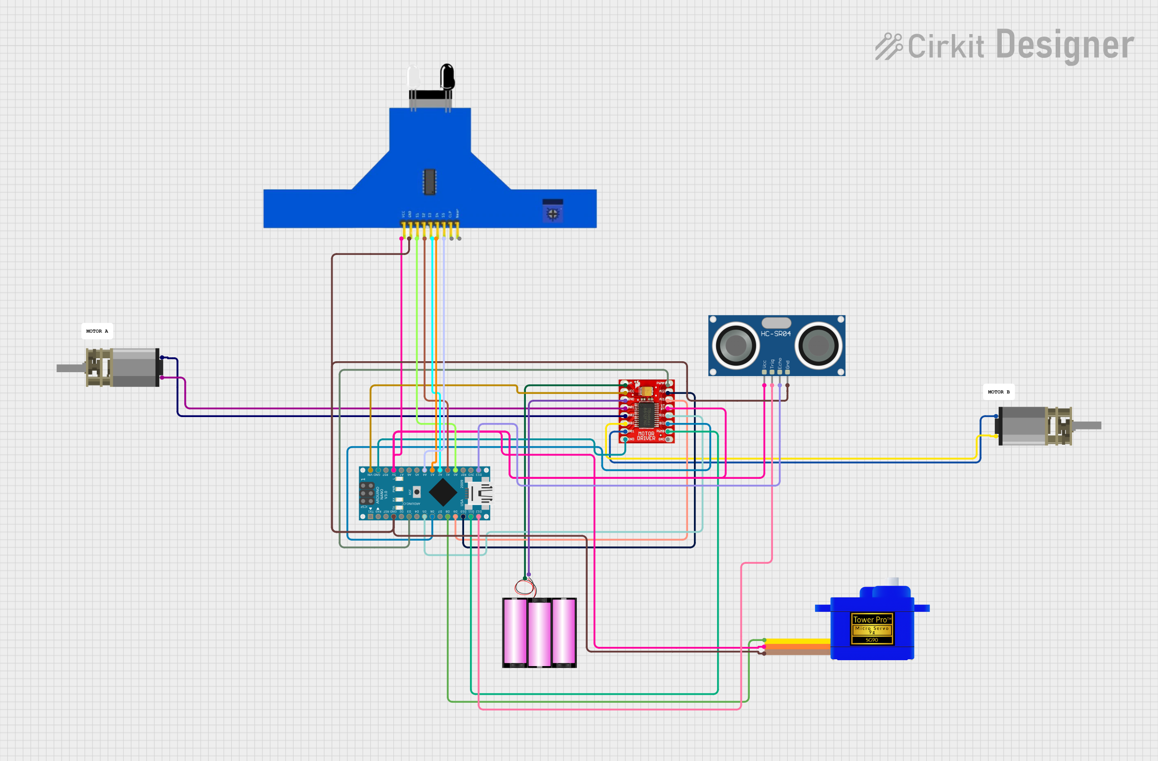
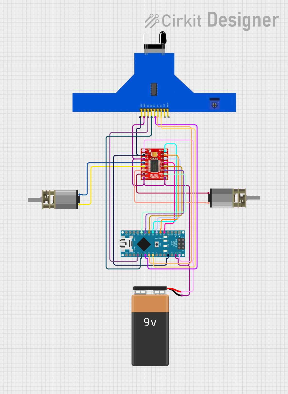
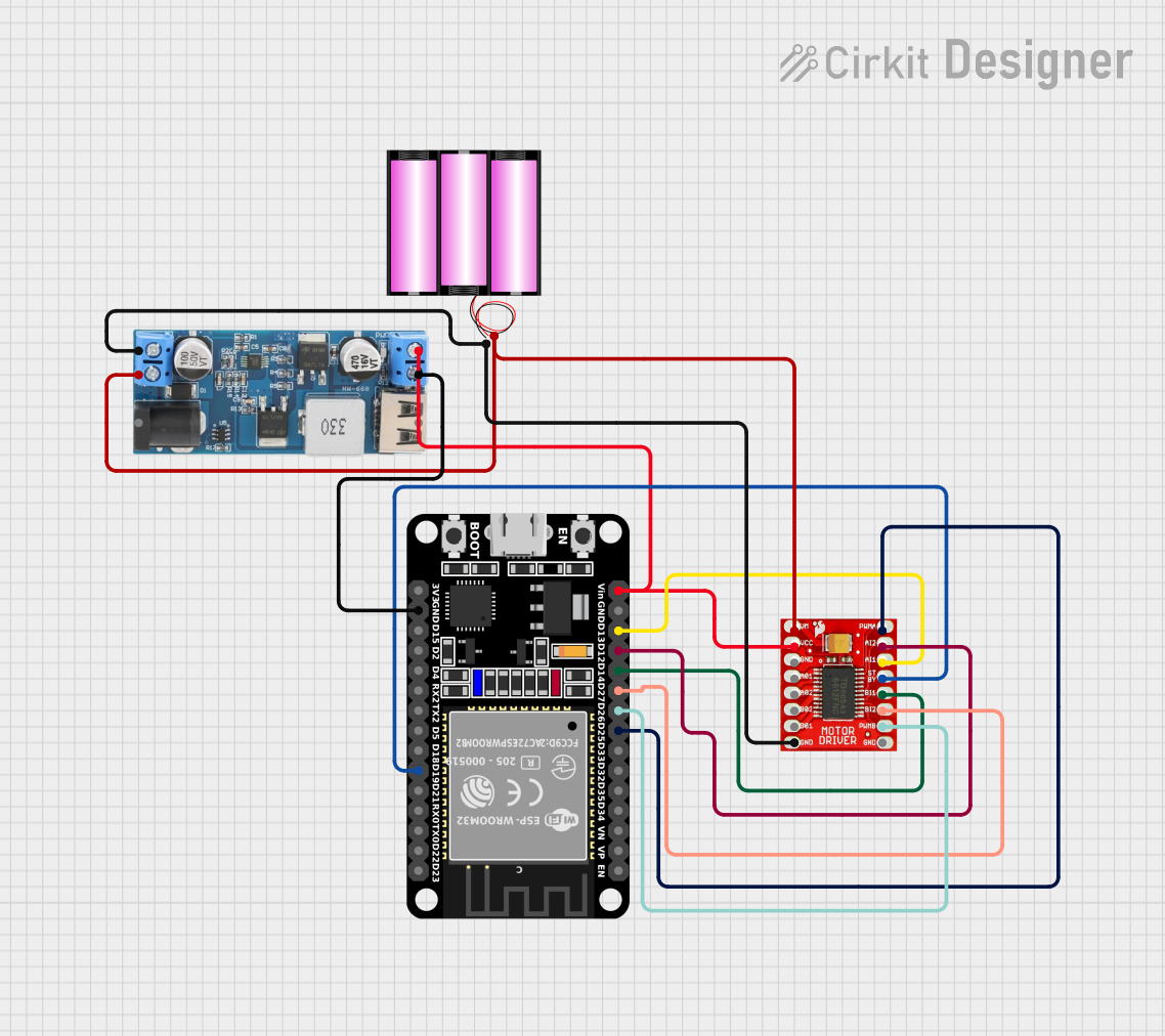
Explore Projects Built with TB6612FNG Motor Driver
Common Applications and Use Cases
- Robotics
- Automated Guided Vehicles (AGVs)
- Hobbyist projects
- Educational platforms
- Small electric vehicles
- CNC machines and 3D printers (for stepper motor control)
Technical Specifications
Key Technical Details
- Supply Voltage (VM): 2.5V to 13.5V
- Logic Voltage (VCC): 2.7V to 5.5V
- Output Current (continuous): 1.2A per channel
- Output Current (peak): 3.2A per channel
- Standby Control to save power
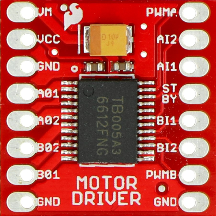
Pin Configuration and Descriptions
| Pin Number | Pin Name | Description |
|---|---|---|
| 1 | VM | Motor power supply input (2.5V to 13.5V) |
| 2 | VCC | Logic power supply input (2.7V to 5.5V) |
| 3 | GND | Ground |
| 4 | STBY | Standby control input (Low: Standby, High: Active) |
| 5-6 | AIN1, AIN2 | Motor A input control pins |
| 7-8 | BIN1, BIN2 | Motor B input control pins |
| 9-10 | A01, A02 | Motor A output pins |
| 11-12 | B01, B02 | Motor B output pins |
| 13 | PWMA | PWM input for motor A speed control |
| 14 | PWMB | PWM input for motor B speed control |
Usage Instructions
How to Use the Component in a Circuit
Power Connections:
- Connect the VM pin to your motor power supply (up to 13.5V).
- Connect the VCC pin to your logic power supply (2.7V to 5.5V).
- Connect all GND pins to the common ground of your power supplies and control logic.
Motor Connections:
- Connect your DC motors to the A01/A02 and B01/B02 output pins for motor A and B, respectively.
Control Connections:
- Connect AIN1 and AIN2 to your control logic for motor A direction.
- Connect BIN1 and BIN2 to your control logic for motor B direction.
- Connect PWMA and PWMB to PWM-capable pins on your microcontroller for speed control.
Standby Mode:
- Connect the STBY pin to a digital output on your microcontroller. Set it high to enable the motor driver or low to put it in standby mode.
Important Considerations and Best Practices
- Ensure that the power supply voltage does not exceed the maximum ratings for VM and VCC.
- Use PWM signals for speed control to achieve variable motor speeds.
- Always put the driver in standby mode when not in use to conserve power.
- Provide adequate cooling if the driver is expected to handle currents near the peak ratings.
Example Code for Arduino UNO
// Example code to control a DC motor with the TB6612FNG using an Arduino UNO

#include <Arduino.h>

// Define control pins for Motor A
const int PWMA = 3; // PWM control (speed)
const int AIN1 = 4; // Direction
const int AIN2 = 5; // Direction
const int STBY = 6; // Standby control

void setup() {
  // Set control pins as outputs
  pinMode(PWMA, OUTPUT);
  pinMode(AIN1, OUTPUT);
  pinMode(AIN2, OUTPUT);
  pinMode(STBY, OUTPUT);

  // Disable standby mode
  digitalWrite(STBY, HIGH);
}

void loop() {
  // Set motor A direction to forward
  digitalWrite(AIN1, HIGH);
  digitalWrite(AIN2, LOW);

  // Ramp up the speed
  for (int speed = 0; speed <= 255; speed++) {
    analogWrite(PWMA, speed);
    delay(10);
  }

  // Ramp down the speed
  for (int speed = 255; speed >= 0; speed--) {
    analogWrite(PWMA, speed);
    delay(10);
  }

  // Change direction to backward
  digitalWrite(AIN1, LOW);
  digitalWrite(AIN2, HIGH);

  // Repeat the ramp up and down
  // ... (same as above)
}
Troubleshooting and FAQs
Common Issues
- Motor not moving: Check power supply connections, ensure STBY pin is set high, and verify that the control inputs are correctly configured.
- Motor moving erratically: Ensure PWM signals are clean and within the correct voltage range. Check for loose connections.
- Overheating: Make sure the current through the motor driver does not exceed the continuous current rating. Improve cooling if necessary.
Solutions and Tips for Troubleshooting
- Use a multimeter to check for proper voltage levels at the power supply and control pins.
- If using PWM, verify the frequency and duty cycle are within the specifications.
- Ensure that the logic ground and power ground are connected to a common ground point.
FAQs
Q: Can I control a stepper motor with the TB6612FNG? A: Yes, the TB6612FNG can control a bipolar stepper motor by appropriately toggling the input control pins to create the required stepping sequence.
Q: What is the maximum frequency for the PWM input? A: The TB6612FNG can typically handle PWM frequencies up to 100kHz, but for most applications, a frequency between 1kHz and 20kHz is sufficient.
Q: How do I put the motor driver into standby mode? A: Set the STBY pin to a low logic level to put the TB6612FNG into standby mode, which reduces power consumption when the motors are not in use.
This documentation provides a comprehensive guide to using the TB6612FNG motor driver. For further information, consult the manufacturer's datasheet and application notes.