Cirkit Designer Logo
Cirkit Designer
Your all-in-one circuit design IDE
Home / 
Component Documentation

How to Use XL6009 Auto Step Up Down COnverter: Examples, Pinouts, and Specs

Image of XL6009 Auto Step Up Down COnverter
Cirkit Designer LogoDesign with XL6009 Auto Step Up Down COnverter in Cirkit Designer

XL6009 Auto Step Up Down Converter Documentation

1. Introduction

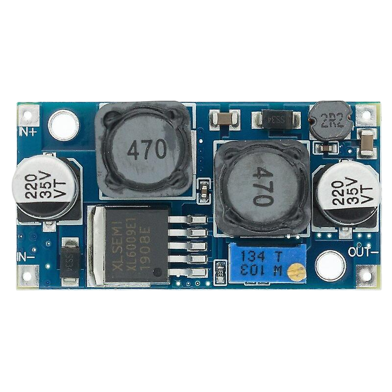
The XL6009 Auto Step Up Down Converter, manufactured by Voltage, is a versatile DC-DC converter designed to either step up or step down the input voltage to a stable output voltage. This component is widely used in power supply circuits where a consistent voltage is required despite variations in the input voltage. Its ability to handle a broad range of input voltages makes it ideal for applications such as battery-powered devices, solar power systems, and automotive electronics.

2. Technical Specifications

Key Technical Details

Parameter Value
Input Voltage 3V to 32V
Output Voltage 1.25V to 35V
Output Current 2A (max)
Efficiency Up to 94%
Switching Frequency 400kHz
Operating Temperature -40°C to +85°C
Dimensions 43mm x 21mm x 14mm

Pin Configuration and Descriptions

Pin Number Pin Name Description
1 VIN Input Voltage (3V to 32V)
2 GND Ground
3 VOUT Output Voltage (1.25V to 35V)
4 EN Enable Pin (Active High)
5 FB Feedback Pin (for setting output voltage)

3. Usage Instructions

How to Use the XL6009 in a Circuit

  1. Connect the Input Voltage:

    • Connect the positive terminal of your input power source to the VIN pin.
    • Connect the negative terminal of your input power source to the GND pin.
  2. Set the Output Voltage:

    • Use a potentiometer connected to the FB pin to adjust the output voltage.
    • Measure the output voltage at the VOUT pin and adjust the potentiometer until the desired voltage is achieved.
  3. Enable the Converter:

    • Connect the EN pin to a high logic level (typically the same voltage as VIN) to enable the converter.
    • To disable the converter, connect the EN pin to a low logic level (GND).

Important Considerations and Best Practices

  • Heat Dissipation: Ensure adequate heat dissipation, especially when operating at high currents. Use a heat sink if necessary.
  • Input Voltage Range: Always ensure the input voltage is within the specified range (3V to 32V) to avoid damaging the converter.
  • Output Voltage Adjustment: Use a precise multimeter to measure the output voltage when adjusting the potentiometer.
  • Capacitors: Use appropriate input and output capacitors to stabilize the voltage and reduce noise.

Example Circuit with Arduino UNO

Here is an example of how to connect the XL6009 to an Arduino UNO to power it with a stable 5V output:

/*
 * Example code to demonstrate the use of XL6009 with Arduino UNO.
 * This code does not interact with the XL6009 directly but shows
 * how to power the Arduino using the converter.
 */

void setup() {
  // Initialize serial communication for debugging
  Serial.begin(9600);
  Serial.println("Arduino powered by XL6009 Converter");
}

void loop() {
  // Your main code here
}

4. Troubleshooting and FAQs

Common Issues and Solutions

  1. No Output Voltage:

    • Solution: Check the input voltage to ensure it is within the specified range. Verify all connections, especially the VIN and GND pins.
  2. Output Voltage Fluctuations:

    • Solution: Ensure that the input voltage is stable. Add input and output capacitors to filter out noise and stabilize the voltage.
  3. Overheating:

    • Solution: Ensure proper ventilation and consider adding a heat sink to the converter. Check if the current draw is within the specified limit (2A max).

FAQs

Q1: Can the XL6009 be used to power a Raspberry Pi?

  • A1: Yes, the XL6009 can be used to power a Raspberry Pi. Ensure the output voltage is set to 5V and the current rating is sufficient for the Raspberry Pi model you are using.

Q2: How do I adjust the output voltage?

  • A2: Use a potentiometer connected to the FB pin to adjust the output voltage. Measure the output voltage with a multimeter and adjust the potentiometer until the desired voltage is achieved.

Q3: What is the efficiency of the XL6009?

  • A3: The efficiency of the XL6009 can be up to 94%, depending on the input and output voltage conditions.

By following this documentation, users can effectively utilize the XL6009 Auto Step Up Down Converter in their projects, ensuring stable and reliable power supply solutions.

Explore Projects Built with XL6009 Auto Step Up Down COnverter

Use Cirkit Designer to design, explore, and prototype these projects online. Some projects support real-time simulation. Click "Open Project" to start designing instantly!
Battery-Powered DC Generator with XL4015 Buck Converter
Image of conveyor: A project utilizing XL6009 Auto Step Up Down COnverter in a practical application
This circuit consists of a 12V battery connected to a rocker switch, which controls the input to an XL4015 DC Buck Step-down converter. The converter steps down the voltage to power a DC generator, with the generator's output connected back to the converter to form a feedback loop.
Cirkit Designer LogoOpen Project in Cirkit Designer
Battery-Powered UPS with Step-Down Buck Converter and BMS
Image of Mini ups: A project utilizing XL6009 Auto Step Up Down COnverter in a practical application
This circuit is a power management system that steps down a 240V AC input to a lower DC voltage using a buck converter, which then powers a 40W UPS. The UPS is controlled by a rocker switch and is backed up by a battery management system (BMS) connected to three 3.7V batteries in series, ensuring continuous power supply.
Cirkit Designer LogoOpen Project in Cirkit Designer
ESP32-Based Smart Energy Monitoring and Control System
Image of SMART SOCKET: A project utilizing XL6009 Auto Step Up Down COnverter in a practical application
This circuit is designed to monitor AC voltage and current using ZMPT101B and ZMCT103C sensors, respectively, with an ESP32 microcontroller processing the sensor outputs. The XL4015 step-down module regulates the power supply to provide a stable voltage to the sensors, the ESP32, and an LCD I2C display. The ESP32 controls a 4-channel relay module for switching AC loads, and the system's operation can be interacted with via the LCD display and a push switch.
Cirkit Designer LogoOpen Project in Cirkit Designer
Dual Motor Control Circuit with Directional Switching and Voltage Regulation
Image of Pencuci Kipas: A project utilizing XL6009 Auto Step Up Down COnverter in a practical application
This circuit features a 12V battery connected through a rocker switch to two buck converters, one of which steps down the voltage to power two DC mini metal gear motors, and the other is connected to a directional switch that controls a third DC mini metal gear motor. The XL4015 5A DC Buck Step-down converter's output is connected to two motors, allowing them to run at a reduced voltage, while the other buck converter's output is routed through a directional switch to control the direction of the third motor.
Cirkit Designer LogoOpen Project in Cirkit Designer

Explore Projects Built with XL6009 Auto Step Up Down COnverter

Use Cirkit Designer to design, explore, and prototype these projects online. Some projects support real-time simulation. Click "Open Project" to start designing instantly!
Image of conveyor: A project utilizing XL6009 Auto Step Up Down COnverter in a practical application
Battery-Powered DC Generator with XL4015 Buck Converter
This circuit consists of a 12V battery connected to a rocker switch, which controls the input to an XL4015 DC Buck Step-down converter. The converter steps down the voltage to power a DC generator, with the generator's output connected back to the converter to form a feedback loop.
Cirkit Designer LogoOpen Project in Cirkit Designer
Image of Mini ups: A project utilizing XL6009 Auto Step Up Down COnverter in a practical application
Battery-Powered UPS with Step-Down Buck Converter and BMS
This circuit is a power management system that steps down a 240V AC input to a lower DC voltage using a buck converter, which then powers a 40W UPS. The UPS is controlled by a rocker switch and is backed up by a battery management system (BMS) connected to three 3.7V batteries in series, ensuring continuous power supply.
Cirkit Designer LogoOpen Project in Cirkit Designer
Image of SMART SOCKET: A project utilizing XL6009 Auto Step Up Down COnverter in a practical application
ESP32-Based Smart Energy Monitoring and Control System
This circuit is designed to monitor AC voltage and current using ZMPT101B and ZMCT103C sensors, respectively, with an ESP32 microcontroller processing the sensor outputs. The XL4015 step-down module regulates the power supply to provide a stable voltage to the sensors, the ESP32, and an LCD I2C display. The ESP32 controls a 4-channel relay module for switching AC loads, and the system's operation can be interacted with via the LCD display and a push switch.
Cirkit Designer LogoOpen Project in Cirkit Designer
Image of Pencuci Kipas: A project utilizing XL6009 Auto Step Up Down COnverter in a practical application
Dual Motor Control Circuit with Directional Switching and Voltage Regulation
This circuit features a 12V battery connected through a rocker switch to two buck converters, one of which steps down the voltage to power two DC mini metal gear motors, and the other is connected to a directional switch that controls a third DC mini metal gear motor. The XL4015 5A DC Buck Step-down converter's output is connected to two motors, allowing them to run at a reduced voltage, while the other buck converter's output is routed through a directional switch to control the direction of the third motor.
Cirkit Designer LogoOpen Project in Cirkit Designer